
Page 257 - System on Package_ Miniaturization of the Entire System
P. 257
Mixed-Signal (SOP) Design 231
Planar Capacitors with Thin Dielectrics
The planar capacitors are used as power-ground planes, as well as a reference for the
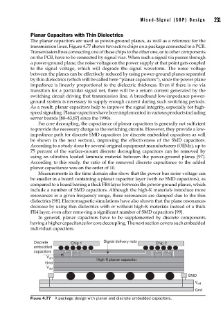
transmission lines. Figure 4.77 shows two active chips on a package connected to a PCB.
Transmission lines connecting one of these chips to the other one, or to other components
on the PCB, have to be connected by signal vias. When such a signal via passes through
a power-ground plane, the noise voltage on the power supply at that point gets coupled
to the signal voltage, which will degrade the signal waveform. The noise voltage
between the planes can be effectively reduced by using power-ground planes separated
by thin dielectrics (which will be called here “planar capacitors”), since the power plane
impedance is linearly proportional to the dielectric thickness. Even if there is no via
transition for a particular signal net, there will be a return current generated by the
switching circuit driving that transmission line. A broadband low-impedance power-
ground system is necessary to supply enough current during such switching periods.
As a result, planar capacitors help to improve the signal integrity, especially for high-
speed signaling. Planar capacitors have been implemented in various products including
server boards [80–83,87] since the 1990s.
For core decoupling, the capacitance of planar capacitors is generally not sufficient
to provide the necessary charge to the switching circuits. However, they provide a low-
impedance path for discrete SMD capacitors (or discrete embedded capacitors as will
be shown in the next section), improving the effectiveness of the SMD capacitors.
According to a study done by several original equipment manufacturers (OEMs), up to
75 percent of the surface-mount discrete decoupling capacitors can be removed by
using an ultrathin loaded laminate material between the power-ground planes [97].
According to this study, the ratio of the removed discrete capacitance to the added
planar capacitance was on the order of 10.
Measurements in the time domain also show that the power bus noise voltage can
be smaller in a board containing a planar capacitor layer (with no SMD capacitors), as
compared to a board having a thick FR4 layer between the power-ground planes, which
include a number of SMD capacitors. Although the high-K materials introduce more
resonances in a given frequency range, these resonances are damped due to the thin
dielectrics [98]. Electromagnetic simulations have also shown that the plane resonances
decrease by using thin dielectrics with or without high-K materials instead of a thick
FR4 layer, even after removing a significant number of SMD capacitors [99].
In general, planar capacitors have to be supplemented by discrete components
having a higher capacitance for core decoupling. The next section covers such embedded
individual capacitors.
Discrete Chip 1 Signal delivery nets Chip 2
embedded
capacitors
V dd
High-K planar capacitor
Gnd
V dd
SMD
V dd
Gnd
FIGURE 4.77 A package design with planar and discrete embedded capacitors.