
Page 266 - System on Package_ Miniaturization of the Entire System
P. 266
240 Cha pte r F o u r
been used for achieving RF isolation in antenna design [90]. And more recently,
Kamgaing and Ramahi [91] have used a three-layer “mushroom-type” EBG to suppress
the propagation of SSN in digital applications. With good point-to-point isolations and
the ability to use a single power supply, EBGs have the potential to solve the power-
supply based noise coupling in SOP-based mixed-signal integration.
An EBG structure proposed in [62] provides excellent isolation of more than 60 dB.
This EBG structure consists of a patterned power-ground plane pair and requires no
additional vias, which are necessary in the embedded EBG structure [91]. Therefore,
standard printed circuit board fabrication techniques are easily applicable, which is a
cost-effective solution.
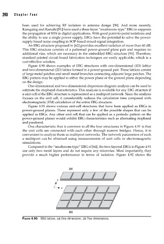
Figure 4.90 shows examples of EBG structures with one-dimensional (1D) lattice
and two-dimensional (2D) lattice formed in a power-ground pair. These lattices consist
of large metal patches and small metal branches connecting adjacent large patches. The
EBG pattern may be applied to either the power plane or the ground plane depending
on the design.
One-dimensional and two-dimensional dispersion-diagram analysis can be used to
estimate the stopband characteristics. This analysis is available for any EBG structure if
a unit cell of the EBG structure is represented as a multiport network. Since the analysis
focuses on the unit cell, it considerably reduces the calculation time compared with
electromagnetic (EM) calculation of the entire EBG structure.
Figure 4.91 shows various unit-cell structures that have been applied as EBGs in
power-ground planes. These represent only a few of the possible shapes that can be
applied as EBGs. Any other unit cell that can be applied as a periodic pattern on the
power-ground planes would exhibit EBG characteristics such as alternating stopband
and passband.
One characteristic that is common to all the four structures in Figure 4.91 is that
the unit cells are connected with each other through narrow bridges. Hence, it is
convenient to analyze them as multiport networks. The network parameters of such
a multiport can be obtained using measurements of unit cells or electromagnetic
simulations.
Compared to the “mushroom-type” EBG of [64], the two-layered EBGs in Figure 4.91
use only two metal layers and do not require any microvias. Most importantly, they
provide a much higher performance in terms of isolation. Figure 4.92 shows the
(a)
y
x
(b)
FIGURE 4.90 EBG lattice. (a) One dimension. (b) Two dimensions.