
Page 267 - System on Package_ Miniaturization of the Entire System
P. 267
Mixed-Signal (SOP) Design 241
w2 w3
g1
w3
g2
w1 w2
w1
(a) (b)
p2 w
g1
a
l 1
d
g3
p1
w g2
1
(c) (d)
FIGURE 4.91 Examples of two-layered EBGs. (a) Alternating impedance EBG. (b) Slit EBG. (c) Low
period coplanar EBG. (d) L-bridged EBG.
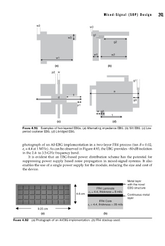
photograph of an AI-EBG implementation in a two-layer FR4 process (tan d = 0.02,
e = 4.4 at 1 MHz). As can be observed in Figure 4.93, the EBG provides ∼80-dB isolation
r
in the 2.4- to 3.5-GHz frequency band.
It is evident that an EBG-based power distribution scheme has the potential for
suppressing power supply based noise propagation in mixed-signal systems. It also
enables the use of a single power supply for the module, reducing the size and cost of
the device.
Metal layer
with the novel
FR4 Laminate EBG structure
ε = 4.4, thickness = 8 mils
r
4.6 cm Continuous metal
layer
FR4 Core
ε = 4.4, thickness = 28 mils
r
9.25 cm
(a) (b)
FIGURE 4.92 (a) Photograph of an AI-EBG implementation. (b) FR4 stackup used.