
Page 276 - System on Package_ Miniaturization of the Entire System
P. 276
250 Cha pte r F o u r
Antenna
EUT
3 m
RF signal
generator
(a)
0
–10 Solid line: test vehicle 1
Dotted line: test vehicle 2
–20 Dashed line: test vehicle 3
Power [dBm] –30
–40
–50
–60
–70
0 0.5 1 1.5 2
Frequency (GHz)
(b)
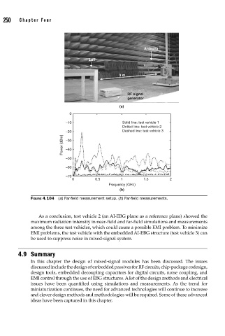
FIGURE 4.104 (a) Far-fi eld measurement setup. (b) Far-fi eld measurements.
As a conclusion, test vehicle 2 (an AI-EBG plane as a reference plane) showed the
maximum radiation intensity in near-field and far-field simulations and measurements
among the three test vehicles, which could cause a possible EMI problem. To minimize
EMI problems, the test vehicle with the embedded AI-EBG structure (test vehicle 3) can
be used to suppress noise in mixed-signal system.
4.9 Summary
In this chapter the design of mixed-signal modules has been discussed. The issues
discussed include the design of embedded passives for RF circuits, chip-package codesign,
design tools, embedded decoupling capacitors for digital circuits, noise coupling, and
EMI control through the use of EBG structures. A lot of the design methods and electrical
issues have been quantified using simulations and measurements. As the trend for
miniaturization continues, the need for advanced technologies will continue to increase
and clever design methods and methodologies will be required. Some of these advanced
ideas have been captured in this chapter.