Page 275 - System on Package_ Miniaturization of the Entire System
P. 275

Mixed-Signal (SOP) Design   249


                                                          9.3 cm


                                          Microstrip line

                               SMA
                            connector                                              4.7 cm

                                                                 Termination: 46 ohms
                                                        1.5 cm   resistor, connected to
                                                                 reference plane


                    FIGURE 4.102  Top view of test vehicle.


                    be seen in the figure. Test vehicles 1 and 2 behave as common microstrip lines, due to
                    the solid reference plane underneath.
                       Far-field measurements have also been done for the test vehicles. The far-field
                    measurements were carried out using the  Anritsu MG3642A RF signal generator
                    (bandwidth: 125 kHz to 2080 MHz), Agilent E4440A spectrum analyzer (bandwidth:
                    3 kHz to 26.5 GHz, and the antenna in anechoic chamber. Figure 4.104a shows the
                    measurement setup for the far-field measurements. Since the RF signal generator works
                    properly up to 2 GHz, the far-field measurements were also done up to 2 GHz. The
                    distance between the equipment under test (EUT) and antenna was 3 m in this case. The
                    RF signal generator was connected to the EUT as a source, and the spectrum analyzer,
                    which was connected to the antenna, recorded the field intensity from the surface of the
                    test vehicles. In this measurement, the radiation intensity from test vehicle 2 is the
                    maximum among three test vehicles, as shown in Figure 4.104b, and test vehicles 1 and
                    3 showed almost the same radiation intensity because a solid plane was used as a
                    reference plane for these two test vehicles.
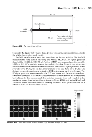

                                                                                  Amps/Meter
                                                                                   13
                                                                                   12
                                                                                   10
                                                                                  0.7
                                                                                  7.2
                                                                                  5.8
                                                                                  4.3
                                                                                  2.9
                                                                                  1.4
                                                                                  0.0
                               (a)                             (b)
               FIGURE 4.103  Simulation result for test vehicle 2: (a) 300 MHz and (b) 2.7 GHz.
   270   271   272   273   274   275   276   277   278   279   280