
Page 132 - Sami Franssila Introduction to Microfabrication
P. 132
Lithographic Patterns 111
spinning process, but on a structured surface there is no those of TARs, but the materials and processes are.
general solution to the variable resist thickness problem BARCs must tolerate developers, because if they did
(Figure 10.5). not, they would undercut the resist patterns. BARCs
Swing ratio is a measure of the variation introduced are therefore patterned by dry-etching. Spin-on polymer-
by thin film–optical effects. It is determined as exposure based BARCs do exist, but inorganic BARCs that will
dose variation (max–min) divided by mean value. It can be left as permanent parts of the finished devices are also
be defined similarly for linewidth. It is analogous to a used. Titanium nitride, TiN, is a BARC for aluminum
lossy Fabry–Perot interferometer, and swing rate can lithography, but it is deposited in the same process as
modelled as the aluminum, not in conjunction with resist process-
S = 4e (−αD) (R 1 R 2 ) (10.4) ing. Oxides and nitrides can also be used as BARCs. It
is difficult to remove them selectively, and most often,
they too remain as parts of finished devices. Inorganic
where R 1 is the reflectivity at the air–resist interface;
BARCs can act as hard masks for etching: the resist is
R 2 is the reflectivity at the resist–substrate
interface; used as mask for BARC etching, and BARC is then used
as a mask for film etching.
α is the resist absorption coefficient; Absorption strategy involves resist tailoring. Standard
D is the resist thickness. −1
αs are around 0.2 to 1 µm . Adding dyes to increase α
Obviously, there are four ways to minimize the to, for example, 2 µm −1 means that all radiation will be
swing ratio. One strategy is to minimize R 1 , which absorbed in the top resist layer, and the bottom part will
translates to a top antireflective coating (TAR). Light not be exposed. So, there is an optimum between swing
traversing TAR twice will interfere destructively and ratio reduction and resist profile. Top-surface imaging
minimize reflections if the TAR thickness matches the (TSI), which will be discussed shortly, overcomes the
λ/4n condition. The TAR refractive index is given by absorption dilemma by using very thin resists, which are
n TAR = (n resist × n air ) 1/2 . With resist n’s typically around not sensitive to profile variation like standard resists.
1.65, the TAR refractive index should be ca. 1.3. The The fourth possibility, resist thickness increase, is at
TAR thickness would then be ca. 70 nm. odds with resolution: if we wish to print narrow lines,
Photoresist-like spinning is a popular method for thinner resists are better. Scaling to smaller linewidths
coating the TAR, and the material is very much with this strategy is therefore not an option at all.
photoresist-like (non-absorbing, however), and it will be
removed by the developer. Added process complexity is
10.3.1 Lithography over steps
small. The TAR is insensitive to the substrate material,
and therefore, this is a fairly general method to reduce Viscous flow of photoresist over steps leads inevitably
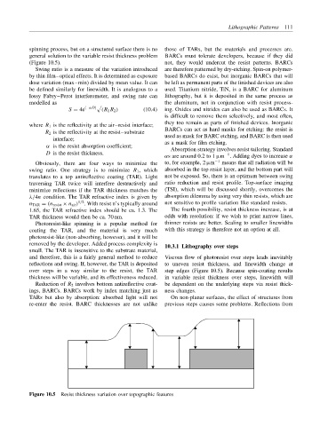
reflections and swing. If, however, the TAR is deposited to uneven resist thickness, and linewidth change at
over steps in a way similar to the resist, the TAR step edges (Figure 10.5). Because spin-coating results
thickness will be variable, and its effectiveness reduced. in variable resist thickness over steps, linewidth will
Reduction of R 2 involves bottom antireflective coat- be dependent on the underlying steps via resist thick-
ings, BARCs. BARCs work by index matching just as ness changes.
TARs but also by absorption: absorbed light will not On non-planar surfaces, the effect of structures from
re-enter the resist. BARC thicknesses are not unlike previous steps causes some problems. Reflections from
Figure 10.5 Resist thickness variation over topographic features