
Page 243 - Sami Franssila Introduction to Microfabrication
P. 243
222 Introduction to Microfabrication
22.5 ROTATING STRUCTURES Bearing clearance
Two structural layers enable rotating structures to be
made. The centre-pin process utilizes two structural
and two sacrificial layers (Figure 22.10). In contrast to
the previous comb-drive example, poly1 becomes the
movable element, and poly2 serves as the fixed element
that bounds the rotating element made of poly1. The
first sacrificial layer defines the gap between substrate
(a)
and poly1, and the second sacrificial layer defines
interpoly gap. Bearing clearance
The concept of self-alignment is useful in released
structures as well. The centre-pin and the rotor can be
Bushing mold
(b)
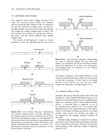
(a) Figure 22.11 Cross-sectional schematics demonstrating
two types of centre-pin bearings that may result after
Bushing Rotor
release: (a) self-aligned and (b) non-self-aligned. Repro-
duced from Mehregany, M. & Dewa, A.S.: http://mems.
cwru.edu/shortcourse/ by permission of Case Western
Reserve University
(b)
self-aligned. It depends on the relative thickness of the
structural and sacrificial layers. Poly2 pin can be made
Bearing anchor
to limit the movements of poly1 rotor in the lateral
direction. In the opposite case, the rotor can wobble
because the centre-pin is too high (Figure 22.11).
(c)
22.6 HINGED STRUCTURES
Bearing
Structures that pop up from the plane of the wafer can
be made by various methods. Mechanical hinges can be
made in a two structural-layer process or with polymeric
hinges in a one-layer process. In the polymeric-hinge
process, a polyimide hinge is patterned on top of
the structural layers (Figure 22.12). The movable plate
(d) dimensions have to be smaller than those of the anchor,
which can be helped by making perforations for release
Figure 22.10 Cross-sectional schematics demonstrating
the centre-pin bearing process: (a) after patterning of etching. Upon release, the movable poly plate can
be actuated by, for example, thermal expansion of
the bushing mould in the first sacrificial layer; (b) after
deposition and patterning of poly1; (c) after deposition of the imide.
the second sacrificial layer and anchor region definition and Alternative hinge technology is based on two polysil-
(d) deposition and patterning of poly2, followed by oxide icon layers: poly1 forms the moving element and poly2
etching. Reproduced from Mehregany, M. & Dewa, A.S.: forms a staple that lets the poly1 structure rotate upwards
http://mems.cwru.edu/shortcourse/ by permission of Case from the plane of the wafer but confines it otherwise
Western Reserve University (Figure 22.13).