
Page 241 - Sami Franssila Introduction to Microfabrication
P. 241
220 Introduction to Microfabrication
(SD)
(C)
(a) (b) Solid Liquid
Figure 22.5 Three-mask process for cantilever with dim- Pressure (I)
ples: (a) first mask step for anchor area etching; second (FD)
mask step for dimple etching and (b) structural-layer depo-
sition, lithography and etching (T) (ND)
Gas
(F)
rinsing water is replaced by tert-butanol, and then
frozen. Heating is performed under reduced pres- Temperature
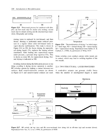
sure in a regime where solid tert-butanol turns to Figure 22.6 Thermodynamics of drying: I = initial stage;
vapor directly (sublimation). This route is shown in F = final stage; ND = normal drying; FD = freeze drying;
Figure 22.6 as FD, for freeze drying. In supercriti- SD = supercritical drying. Reproduced from Bellet, D. &
cal drying liquid, CO 2 replaces the rinsing solvent Canham, L. (1998), by permission of Wiley-VCH
(methanol). After heating into supercritical region
under pressure, a pressure drop vaporizes CO 2 . This
is shown as route SD, for supercritical drying. Nor- Some switches even conduct current while metals are
mal drying is indicated as ND. in contact, which may lead to welding together of the
two metals.
Avoiding stiction during the fabrication process is one
thing; avoiding it during device operation is another. 22.4 TWO STRUCTURAL–LAYER PROCESSES
RF switches operate by making a contact between two
surfaces. Both metal-to-dielectric contacts (as shown A comb-drive actuator can generate sizable forces
in Figure 22.7) and metal-to-metal contacts are used. when the number of interdigitated fingers is made
Membrane
Dielectric
Electrode
A
Suspended
membrane Substrate
(a)
Ground
Electrode
RF RF
input output
Dielectric
Ground
(b)
A
Figure 22.7 RF switch: (a) top view and (b) cross-sectional view along AA in off-state (up) and on-state (down).
Reproduced from Yao, Z.J. et al. (1999), by permission of IEEE