
Page 132 - Low Temperature Energy Systems with Applications of Renewable Energy
P. 132
Effective use of heat pumps for various heating applications 121
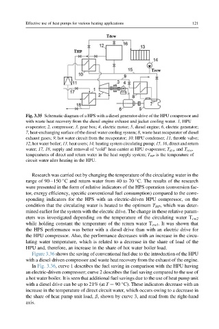
Fig. 3.35 Schematic diagram of a HPS with a diesel generator-drive of the HPU compressor and
with waste heat recovery from the diesel engine exhaust and jacket cooling water. 1, HPU
evaporator; 2, compressor; 3, gear box; 4, electric motor; 5, diesel engine; 6, electric generator;
7, heat-exchanging surface of the diesel water cooling system; 8, waste heat recuperator of diesel
exhaust gases; 9, hot water circuit from the recuperator; 10, HPU condenser; 11, throttle valve;
12, hot water boiler; 13, heat users; 14, heating system circulating pump; 15, 16, direct and return
water; 17, 18, supply and removal of “cold” heat-carrier at HPU evaporator; T dcw and T rcw ,
temperatures of direct and return water in the heat supply system; T HP is the temperature of
circuit water after heating in the HPU.
Research was carried out by changing the temperature of the circulating water in the
range of 90e150 C and return water from 40 to 70 C. The results of the research
were presented in the form of relative indicators of the HPS operation (conversion fac-
tor, exergy efficiency, specific conventional fuel consumption) compared to the corre-
sponding indicators for the HPS with an electric-driven HPU compressor, on the
condition that the circulating water is heated to the optimum T HP , which was deter-
mined earlier for the system with the electric drive. The change in these relative param-
eters was investigated depending on the temperature of the circulating water T cw2
while holding constant the temperature of the return water T cw1 . It was shown that
the HPS performance was better with a diesel drive than with an electric drive for
the HPU compressor. Also, the performance decreases with an increase in the circu-
lating water temperature, which is related to a decrease in the share of load of the
HPU and, therefore, an increase in the share of hot water boiler load.
Figure 3.36 shows the saving of conventional fuel due to the introduction of the HPU
with a diesel-driven compressor and waste heat recovery from the exhaust of the engine.
In Fig. 3.36, curve 1 describes the fuel saving in comparison with the HPU having
an electric-driven compressor; curve 2 describes the fuel saving compared to the use of
a hot water boiler. It is seen that additional fuel savings due to the use of heat pump unit
with a diesel drive can be up to 21% (at T ¼ 90 C). These indicators decrease with an
increase in the temperature of direct circuit water, which occurs owing to a decrease in
the share of heat pump unit load, b, shown by curve 3, and read from the right-hand
axis.