
Page 343 -
P. 343
X-Ray–Based Fabrication 5-5
1
0.8
Transmission 0.6 C (2um)
Si5N (1um)
0.4
Ti (2um)
Si (2um)
Be (100um)
0.2
C(G) (100um)
Si (100um)
0
2 3 4 5 6 7 8 9 10 20
Enegry (kev)
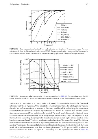
FIGURE 5.3 X-ray transmission of various X-ray mask substrates as a function of X-ray photon energy. The non-
stoichiometric form of silicon nitride is a low stress LPCVD (low pressure chemical vapor deposition) form used in
membrane fabrication. For the carbon mask at 100µm thickness, graphite with a density of 1.65g/cc was used.
3 10 13 Aladdin-1.0 GeV
Flux (photons/sec/mrad 2 /0.1%BW) 1.5 10 13 CAMD-1.3 GeV
13
2.5 10
2 10
CAMD-1.5 GeV
ALS-1.9 GeV
13
SSRL-3.0 GeV
NSLS-2.584 GeV
13
1 10
CAMD-1.5 GeV wiggler
12
5 10
0 APS - 7 GeV
2 3 4 5 6 7 8 910 20 30
Energy (keV)
FIGURE 5.4 Synchrotron radiation spectra for U.S. storage rings listed in Table 5.1. The spectral curve for the APS
14
2
source, which has a peak flux near 1(10) photons/sec/mrad /0.1%BW at 16keV, does not appear on the graph.
[Sekimoto et al., 1982; Visser et al., 1987; Guckel et al., 1989]. The transmission behavior for these mask
substrates is plotted in Figure 5.3. What is needed is a mask substrate that is stable to large X-ray flux and
that also has sufficient thickness or support to allow easy handling while maintaining the transmission
3
necessarytoreadily achieve the required exposure dose. For PMMA the required dose is near 3 kJ/cm .
Acorresponding source of X-ray radiation is also required.The nearly ideal light source for this task is found
in the synchrotron radiation (SR) that is emitted by charged particle storage rings. The properties of light
that result from accelerating charged particles at relativistic energies include highly intense radiation over a
broad spectral range from UV to X-ray wavelengths and collimation of the order of 0.1 mrad. The SR beam
is emitted in a narrow horizontal stripe of light through a vacuum line (beamline)extending from the stor-
age ring. This requires the mask and photoresist combination to be scanned vertically through the beam,
which additionally determines a local dose rate in the photoresist. The SR spectra for U.S. synchrotron
radiation facilities are plotted in Figure 5.4. Frequently used SR equations are listed in Table 5.3
© 2006 by Taylor & Francis Group, LLC