Page 435 -
P. 435
7-24                                                             MEMS: Design and Fabrication


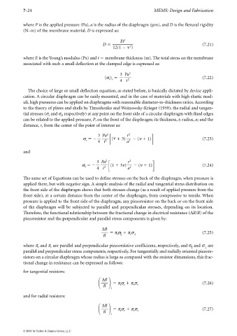
             where P is the applied pressure (Pa), a is the radius of the diaphragm (µm), and D is the flexural rigidity
             (N–m) of the membrane material. D is expressed as:

                                                             Et 3
                                                     D                                                 (7.21)
                                                                  2
                                                          12(1   ν )

             where E is the Young’s modulus (Pa) and t   membrane thickness (m). The total stress on the membrane
             associated with such a small deflection at the clamped edge is expressed as:


                                                             3  Pa 2
                                                      (σ )                                             (7.22)
                                                        r r  4  t 2

               The choice of large or small deflection equation, as stated before, is basically dictated by device appli-
             cation. A circular diaphragm can be easily mounted, and in the case of materials with high elastic mod-
             uli, high pressures can be applied on diaphragms with reasonable diameter-to-thickness ratios. According
             to the theory of plates and shells by Timoshenko and Woinowsky-Krieger (1959), the radial and tangen-
             tial stresses (σ and σ , respectively) at any point on the front side of a circular diaphragm with fixed edges
                         r      t
             can be related to the applied pressure, P, on the front of the diaphragm; its thickness, t; radius, a; and the
             distance, r, from the center of the point of interest as:

                                                  3  Pa 2        r 2
                                           σ              (ν   3)     (ν   1)                          (7.23)
                                            r     4  t 2         a 2

             and

                                                  3  Pa 2        r 2
                                          σ              (1   3ν)     (ν   1)                          (7.24)
                                            t     4  t 2         a 2

             The same set of Equations can be used to define stresses on the back of the diaphragm, when pressure is
             applied there, but with negative sign. A simple analysis of the radial and tangential stress distribution on
             the front side of the diaphragm shows that both stresses change (as a result of applied pressure from the
             front side), at a certain distance from the center of the diaphragm, from compressive to tensile. When
             pressure is applied to the front side of the diaphragm, any piezoresistor on the back or on the front side
             of the diaphragm will be subjected to parallel and perpendicular stresses, depending on its location.
             Therefore, the functional relationship between the fractional change in electrical resistance (∆R/R) of the
             piezoresistor and the perpendicular and parallel stress components is given by:

                                                    ∆R
                                                          π σ   π σ                                    (7.25)
                                                     R      t     r ⊥

             where π and π are parallel and perpendicular piezoresistive coefficients, respectively, and σ and σ are

                                                                                                        ⊥
                    t
                          r
             parallel and perpendicular stress components, respectively. For tangentially and radially oriented piezore-
             sistors on a circular diaphragm whose radius is large as compared with the resistor dimensions, this frac-
             tional change in resistance can be expressed as follows:
             for tangential resistors:
                                                            π σ   π σ                                  (7.26)
                                                    ∆R

                                                             t t
                                                                    r r
                                                     R
                                                         t
             and for radial resistors:
                                                            π σ   π σ                                  (7.27)
                                                    ∆R

                                                                    r t
                                                             t r
                                                     R
                                                         r
             © 2006 by Taylor & Francis Group, LLC

