
Page 495 -
P. 495
2 mm
X
Die attach material
0.29 SiC die
20 micron Au
0.635 AlN or Al O substrate
2 3
4 mm
Side view of die-attach
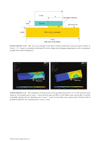
COLOR FIGURE 12.18 Side view of an example of die-attach structure with lateral stress attenuation. Where X
(0mm X 2mm) is a parameter determined by device design and packaging requirements, such as mechanical
strength and resonant frequencies.
Attached
Attached
COLOR FIGURE 12.19 FEA simulation of thermal stress of the partially attached SiC die on AlN substrate using
20µm Au. The attached area is 1 mm 1 mm. All stress units are MPa. (a) Von-Mises stress contour plot of top half
of partially attached SiC die. Attaching area is 1 mm 1mm. (b) Von-Mises stress contour plot of bottom half of
partially attached SiC die. Attaching area is 1mm 1mm.
© 2006 by Taylor & Francis Group, LLC