
Page 499 -
P. 499
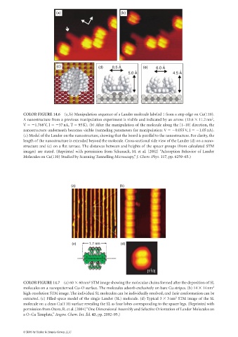
(a)                              (b)


                             (c)                  (d)    8.5 A °         (e)   6.0 A °
                                                                     °                     °
                                                                 5.0 A                 4.5 A


             COLOR FIGURE 14.6 (a, b) Manipulation sequence of a Lander molecule labeled 1 from a step edge on Cu(110).
                                                                                                           2
             A nanostructure from a previous manipulation experiment is visible and indicated by an arrow. (13.6   11.2 nm ,
             V    1.768V, I    37nA, T   95K). (b) After the manipulation of the molecule along the [1–10] direction, the
             nanostructure underneath becomes visible (tunneling parameters for manipulation: V    0.055 V, I    1.05 nA).
             (c) Model of the Lander on the nanostructure, showing that the board is parallel to the nanostructure. For clarity, the
             length of the nanostructure is extended beyond the molecule. Cross-sectional side view of the Lander (d) on a nano-
             structure and (e) on a flat terrace. The distances between and heights of the spacer groups (from calculated STM
             images) are stated. (Reprinted with permission from Schunack, M. et al. [2002] “Adsorption Behavior of Lander
             Molecules on Cu(110) Studied by Scanning Tunnelling Microscopy,” J. Chem. Phys. 117, pp. 6259–65.)


                                     (a)                     (b)


                                     (c)      1.7 nm         (d)


                                                                            -
                                                                           [110]

                                              2
             COLOR FIGURE 14.7 (a) 60   60nm STM image showing the molecular chains formed after the deposition of SL
             molecules on a nanopatterned Cu–O surface. The molecules adsorb exclusively on bare Cu stripes. (b) 14   14 nm 2
             high-resolution STM image. The individual SL molecules can be individually resolved, and their conformation can be
             extracted. (c) Filled-space model of the single Lander (SL) molecule. (d) Typical 3   3nm STM image of the SL
                                                                                         2
             molecule on a clean Cu(110) surface revealing the SL as four lobes corresponding to the spacer legs. (Reprinted with
             permission from Otero, R. et al. [2004] “One Dimensional Assembly and Selective Orientation of Lander Molecules on
             a O–Cu Template,” Angew. Chem. Int. Ed. 43, pp. 2092–95.)


             © 2006 by Taylor & Francis Group, LLC