
Page 419 - 04. Subyek Engineering Materials - Manufacturing, Engineering and Technology SI 6th Edition - Serope Kalpakjian, Stephen Schmid (2009)
P. 419
Section 16.5 Bending Sheets, Plates, and Tubes 399
see hydrostatic stress, Section 2.2.8). Bendability also depends on 20
the edge condition of the sheet. Since rough edges are points of stress
concentration, bendability decreases as edge roughness increases. if 15
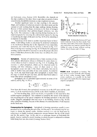
Another significant factor in edge cracking is the amount, é g 5 = (eo/r) -1
shape, and hardness of inclusions present in the sheet metal and the S 2 10 T
amount of cold working that the edges undergo during shearing. g 5
Because of their pointed shape, inclusions in the form of stringers cn if 5
are more detrimental than globular-shaped inclusions (see also m N ° 0 :
0 u 0
Fig. 2.23). The resistance to edge cracking during bending can be
O 10 20 30 40 50 60 70
improved greatly by removing the cold-worked regions by shaving
Tensile reduction of area (%)
or machining the edges of the part (see Fig. 16.9) or by annealing it
to improve its ductility. FIGURE l6.|8
Anisotropy of the sheet is another important factor in bend- Relationship between R/T and
tensile reduction of area for sheet metals. Note
ability. Cold rolling results in anisotropy by preferred orientation
that sheet metal with a 50% tensile reduction of
or by mechanical #bering due to the alignment of any impurities,
area can be bent over itself in a process like the
inclusions, and voids that may be present, as shown in Fig. 1.13.
folding of a piece of paper without cracking.
Prior to laying out or nesting (see Fig. 16.55 ) blanks for subsequent Source: After ]. Datsko and CT Yang.
bending, caution should be exercised to cut in the proper direction
from a rolled sheet; however, this choice may not always be possi-
ble in practice. _ i
T
Springback. Because all materials have a finite modulus of elas- / 1/ l | T
ticity, plastic deformation always is followed by some elastic re- After/' Fi ai :
covery when the load is removed (see Fig. 2.3). In bending, this /
recovery is called springback, which can be observed easily by at X75 sl Rf \`af
`,»|
bending and then releasing a piece of sheet metal or wire. “TV Before `°\i
Springback occurs not only in flat sheets and plates, but also in
solid or hollow bars and tubes of any cross section. As noted in
FIGURE l6.I9 Springback in bending. The
Fig. 16.19, the final bend angle after springback is smaller than
part tends to recover elastically after bending,
the angle to which the part was bent, and the final bend radius is
and its bend radius becomes larger. Under
larger than before springback occurs. certain conditions, it is possible for the final
Springback can be calculated approximately in terms of the bend angle to be smaller than the original angle
radii R, and Rf (Fig. 16.19) as (negative springback).
& _ 4<M>3 ,(%) + 1 (16.6)
Rf _ ET ET '
Note from this formula that springback increases (a) as the R/T ratio and the yield
stress, Y, of the material increase and (b) as the elastic modulus, E, decreases.
In V-die bending (Figs. 16.20 and 16.21), it is possible for the material to also
exhibit negative springback. This condition is caused by the nature of the deforma-
tion occurring just as the punch completes the bending operation at the end of the
stroke. Negative springback does not occur in air bending, shown in Fig. 16.22a
(also called free bending), because of the absence of constraints that a V-die imposes
on the bend area.
Compensation for Springback. Springback in forming operations usually is com-
pensated for by oz/erbending the part (Figs. 16.20a and b). Several trials may be nec-
essary to obtain the desired results. Another method is to coin the bend area by
subjecting it to highly localized compressive stresses between the tip of the punch
and the die surface (Figs. 16.20c and d)-a technique known as hottonzing the
punch. Another method is stretch bending, in which the part is subjected to tension
while being bent (see also stretch forming, Section 16.6 ).