
Page 422 - 04. Subyek Engineering Materials - Manufacturing, Engineering and Technology SI 6th Edition - Serope Kalpakjian, Stephen Schmid (2009)
P. 422
Ram
Die holder
02 Chapter 16 Sheet-Metal Forming Processes and Equipment
coo sse
gear
T
vw
E
Main Q Flywheel
2, /3),
V _
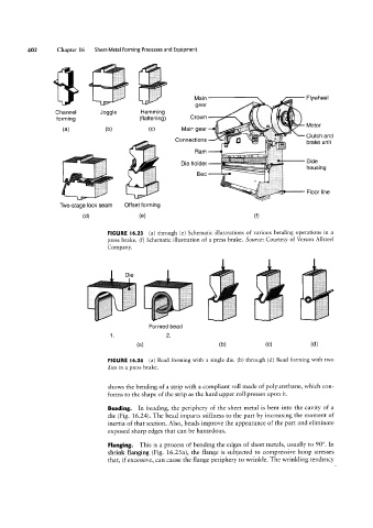
Channel Joggle Hemming f gg
forming (flattening) Crown /" gtg Tig"
_
(a) (b) (C) Main gear Motor
‘ ' "' 4 25 sf”
Connections \‘!(§ Q Clutch and
brake unit
g
~ ' 1 Bed S'de
..t.,
“W
housing
wr Floor line
aw
Two-stage lock seam Offset forming
(dl (9) (f)
FIGURE l6.23 (al through (e) Schematic illustrations of various bending operations in a
press brake. (f) Schematic illustration of a press brake. Source: Courtesy of Verson Allsteel
Company.
"" iiii
..,,.i..,,
.i.».,.
Formed bead
2.
1
(fi) (D) (C) (d)
FIGURE l6.24 (al Bead forming with a single die. (b) through (d) Bead forming with two
dies in a press brake.
shows the bending of a strip with a compliant roll made of polyurethane, which con-
forms to the shape of the strip as the hard upper roll presses upon it.
Beading. In beading, the periphery of the sheet metal is bent into the cavity of a
die (Fig. l6.24). The bead imparts stiffness to the part by increasing the moment of
inertia of that section. Also, beads improve the appearance of the part and eliminate
exposed sharp edges that can be hazardous.
Flanging. This is a process of bending the edges of sheet metals, usually to 90°. In
shrink flanging (Fig. 16.25a), the flange is subjected to compressive hoop stresses
that, if excessive, can cause the flange periphery to wrinkle. The wrinkling tendency