
Page 205 - Mastering SolidWorks
P. 205
|
174 CHAPTER 5 Using VisUalization techniqUes
This tool to some extent duplicates the DisplayManager, but it also provides a quick summary
of most of the display information, including Wireframe/Shaded display mode, transparency,
hide/show state, and color. It works in both parts and assemblies, and it’s a highly valuable tool.
Between the DisplayManager and the Display pane, you can easily manage one of the most
confusing areas of the SolidWorks software: Appearances.
Applying Color Automatically to Features
You can use the settings found at Tools ➢ Options ➢ Document Properties ➢ Model Display to
automatically color certain types of features with specific colors. For example, you can color all
Shell features red as you create them.
This function has worked intermittently for many years. For example, you can assign Boss
features to always be red, and that works. You can assign surface features to always be yellow,
and it works for Extrude, Revolve, Planar, Offset, Loft, and Sweep surfaces, but not for Boundary,
Fill, or Ruled.
Using Edge Display Settings
Earlier in this chapter, I discussed the Shaded With Edges display style. Sometimes this method
is useful to see the breaks between faces, especially fillets. It is especially useful in assemblies
when parts are different colors.
Taking this one step further, you can also utilize the tangent edge settings. These settings are
found in the View➢ Display menu and also in the Heads-Up View toolbar. These are the settings:
Tangent Edges Visible: This setting displays tangent edges as solid lines, just like all
other edges.
Tangent Edges As Phantom: This setting displays tangent edges in a phantom line font.
Tangent Edges Removed: This setting displays only nontangent edges.
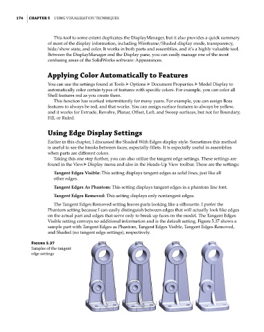
The Tangent Edges Removed setting leaves parts looking like a silhouette. I prefer the
Phantom setting because I can easily distinguish between edges that will actually look like edges
on the actual part and edges that serve only to break up faces on the model. The Tangent Edges
Visible setting conveys no additional information and is the default setting. Figure 5.37 shows a
sample part with Tangent Edges as Phantom, Tangent Edges Visible, Tangent Edges Removed,
and Shaded (no tangent edge settings), respectively.
Figure 5.37
samples of the tangent
edge settings