
Page 333 - Mechanical design of microresonators _ modeling and applications
P. 333
0-07-145538-8_CH06_332_08/30/05
Microcantilever and Microbridge Systems for Mass Detection
332 Chapter Six
1.02
1
r ω
1
0.1
0. 1
c w
c l
0.1
1 1
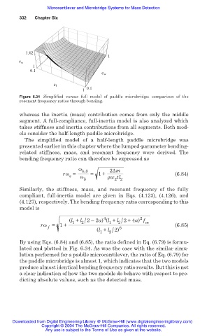
Figure 6.34 Simplified versus full model of paddle microbridge: comparison of the
resonant frequency ratios through bending.
whereas the inertia (mass) contribution comes from only the middle
segment. A full-compliance, full-inertia model is also analyzed which
takes stiffness and inertia contributions from all segments. Both mod-
els consider the half-length paddle microbridge.
The simplified model of a half-length paddle microbridge was
presented earlier in this chapter where the lumped-parameter bending-
related stiffness, mass, and resonant frequency were derived. The
bending frequency ratio can therefore be expressed as
Ȧ b,0 2ǻm
rȦ = = 1+ (6.84)
s
Ȧ
2 2
b ȡw tl
Similarly, the stiffness, mass, and resonant frequency of the fully
compliant, full-inertia model are given in Eqs. (4.123), (4.126), and
(4.127), respectively. The bending frequency ratio corresponding to this
model is
4
2
2/
2/
(l + l 2– 2a) (l + l 2+4a) f m
1
1
rȦ = 1+ (6.85)
f
2/
(l + l 2) 6
1
By using Eqs. (6.84) and (6.85), the ratio defined in Eq. (6.79) is formu-
lated and plotted in Fig. 6.34. As was the case with the similar simu-
lation performed for a paddle microcantilever, the ratio of Eq. (6.79) for
the paddle microbridge is almost 1, which indicates that the two models
produce almost identical bending frequency ratio results. But this is not
a clear indication of how the two models do behave with respect to pre-
dicting absolute values, such as the detected mass.
Downloaded from Digital Engineering Library @ McGraw-Hill (www.digitalengineeringlibrary.com)
Copyright © 2004 The McGraw-Hill Companies. All rights reserved.
Any use is subject to the Terms of Use as given at the website.