
Page 332 - Mechanical design of microresonators _ modeling and applications
P. 332
0-07-145538-8_CH06_331_08/30/05
Microcantilever and Microbridge Systems for Mass Detection
Microcantilever and Microbridge Systems for Mass Detection 331
2
0.5
r m
1
0. 25
0.25
c w
c l 0.01
1 1
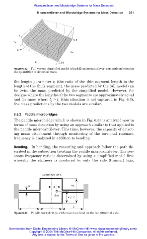
Figure 6.32 Full versus simplified model of paddle microcantilever: comparison between
the quantities of detected mass.
the length parameter c (the ratio of the thin segment length to the
l
length of the thick segment), the mass predicted by the full model can
be twice the mass predicted by the simplified model. However, for
designs where the lengths of the two segments are approximately equal
and for cases where l > l (this situation is not captured in Fig. 6.3),
2
1
the mass predictions by the two models are similar.
6.5.2 Paddle microbridges
The paddle microbridge which is shown in Fig. 6.33 is analyzed now in
terms of mass detection by using an approach similar to that applied to
the paddle microcantilever. This time, however, the capacity of detect-
ing mass attachment through monitoring of the torsional resonant
frequency is analyzed in addition to bending.
Bending. In bending, the reasoning and approach follow the path de-
scribed in the subsection treating the paddle microcantilever. The res-
onant frequency ratio is determined by using a simplified model first
whereby the stiffness is produced by only the side (thinner) legs,
symmetry axis
w 1 a w 2
∆m
w 2 / 2
l 1 l 2 l 1
Figure 6.33 Paddle microbridge with mass localized on the longitudinal axis.
Downloaded from Digital Engineering Library @ McGraw-Hill (www.digitalengineeringlibrary.com)
Copyright © 2004 The McGraw-Hill Companies. All rights reserved.
Any use is subject to the Terms of Use as given at the website.