
Page 185 -
P. 185
5.2 Theoretical Analysis 175
Electric field intensity E x 1.0
1,500 nm x 500 nm
0.5
0
0 2,000 4,000 6,000
Time step
Fig. 5.7. Relationship between electric field E x and time steps of FDTD
4
3
2
1
0
-250 -150 -50 50 150 250 nm
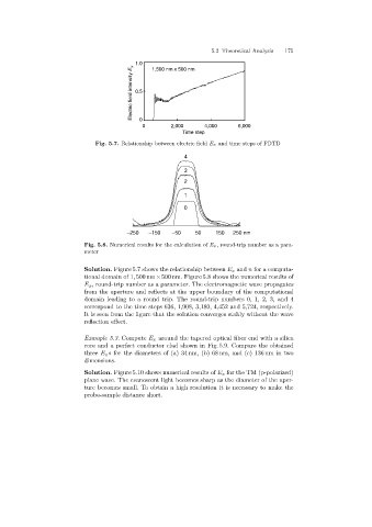
Fig. 5.8. Numerical results for the calculation of E x, round-trip number as a para-
meter
Solution. Figure 5.7 shows the relationship between E x and n for a computa-
tional domain of 1, 500 nm×500 nm. Figure 5.8 shows the numerical results of
E x , round-trip number as a parameter. The electromagnetic wave propagates
from the aperture and reflects at the upper boundary of the computational
domain leadingto a round trip. The round-trip numbers 0, 1, 2, 3, and 4
correspond to the time steps 636, 1,908, 3,180, 4,452 and 5,724, respectively.
It is seen from the figure that the solution converges stably without the wave
reflection effect.
Example 5.3. Compute E x around the tapered optical fiber end with a silica
core and a perfect conductor clad shown in Fig. 5.9. Compare the obtained
three E x s for the diameters of (a) 34 nm, (b) 68 nm, and (c) 136 nm in two
dimensions.
Solution. Figure 5.10 shows numerical results of E x for the TM (p-polarized)
plane wave. The evanescent light becomes sharp as the diameter of the aper-
ture becomes small. To obtain a high resolution it is necessary to make the
probe-sample distance short.