
Page 255 - A Practical Guide from Design Planning to Manufacturing
P. 255
Circuit Design 227
(V) Unity gain points
V out
V iL V iH
V (V)
in
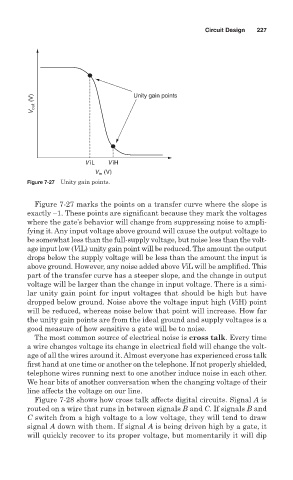
Figure 7-27 Unity gain points.
Figure 7-27 marks the points on a transfer curve where the slope is
exactly −1. These points are significant because they mark the voltages
where the gate’s behavior will change from suppressing noise to ampli-
fying it. Any input voltage above ground will cause the output voltage to
be somewhat less than the full-supply voltage, but noise less than the volt-
age input low (ViL) unity gain point will be reduced. The amount the output
drops below the supply voltage will be less than the amount the input is
above ground. However, any noise added above ViL will be amplified. This
part of the transfer curve has a steeper slope, and the change in output
voltage will be larger than the change in input voltage. There is a simi-
lar unity gain point for input voltages that should be high but have
dropped below ground. Noise above the voltage input high (ViH) point
will be reduced, whereas noise below that point will increase. How far
the unity gain points are from the ideal ground and supply voltages is a
good measure of how sensitive a gate will be to noise.
The most common source of electrical noise is cross talk. Every time
a wire changes voltage its change in electrical field will change the volt-
age of all the wires around it. Almost everyone has experienced cross talk
first hand at one time or another on the telephone. If not properly shielded,
telephone wires running next to one another induce noise in each other.
We hear bits of another conversation when the changing voltage of their
line affects the voltage on our line.
Figure 7-28 shows how cross talk affects digital circuits. Signal A is
routed on a wire that runs in between signals B and C. If signals B and
C switch from a high voltage to a low voltage, they will tend to draw
signal A down with them. If signal A is being driven high by a gate, it
will quickly recover to its proper voltage, but momentarily it will dip