
Page 253 - A Practical Guide from Design Planning to Manufacturing
P. 253
Circuit Design 225
add margin for clock skew. In addition, there will be some variation in the
cycle time of the clock. A 3-GHz processor will attempt to generate a clock
signal at exactly 3 GHz, but the clock generation itself is not perfect.
Variations in process, voltage, and temperature cause the clock frequency
to vary, and this variation in cycle time is called clock jitter. When check-
ing the timing of maxdelay paths from one cycle to the next, margin for clock
jitter must also be included. Because uncertainty in clock timing increases
the requirements on both maxdelay and mindelay, it must be very carefully
controlled for there to be any hope of meeting timing.
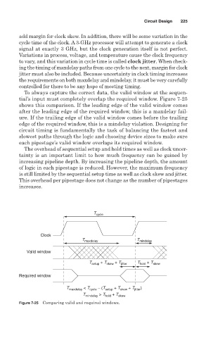
To always capture the correct data, the valid window at the sequen-
tial’s input must completely overlap the required window. Figure 7-25
shows this comparison. If the leading edge of the valid window comes
after the leading edge of the required window, this is a maxdelay fail-
ure. If the trailing edge of the valid window comes before the trailing
edge of the required window, this is a mindelay violation. Designing for
circuit timing is fundamentally the task of balancing the fastest and
slowest paths through the logic and choosing device sizes to make sure
each pipestage’s valid window overlaps its required window.
The overhead of sequential setup and hold times as well as clock uncer-
tainty is an important limit to how much frequency can be gained by
increasing pipeline depth. By increasing the pipeline depth, the amount
of logic in each pipestage is reduced. However, the maximum frequency
is still limited by the sequential setup time as well as clock skew and jitter.
This overhead per pipestage does not change as the number of pipestages
increases.
T cycle
Clock
T maxdelay T mindelay
Valid window
T setup + T skew + T jitter T hold + T skew
Required window
T maxdelay < T cycle − (T setup + T skew + T jitter )
T mindelay > T hold + T skew
Figure 7-25 Comparing valid and required windows.