
Page 248 - A Practical Guide from Design Planning to Manufacturing
P. 248
220 Chapter Seven
Clock
W W
Data Out
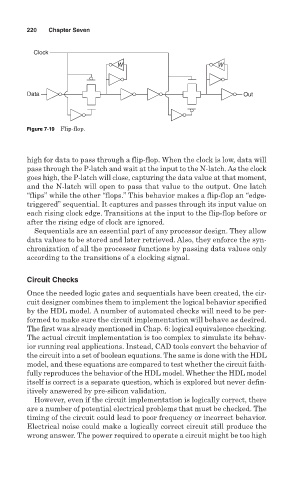
Figure 7-19 Flip-flop.
high for data to pass through a flip-flop. When the clock is low, data will
pass through the P-latch and wait at the input to the N-latch. As the clock
goes high, the P-latch will close, capturing the data value at that moment,
and the N-latch will open to pass that value to the output. One latch
“flips” while the other “flops.” This behavior makes a flip-flop an “edge-
triggered” sequential. It captures and passes through its input value on
each rising clock edge. Transitions at the input to the flip-flop before or
after the rising edge of clock are ignored.
Sequentials are an essential part of any processor design. They allow
data values to be stored and later retrieved. Also, they enforce the syn-
chronization of all the processor functions by passing data values only
according to the transitions of a clocking signal.
Circuit Checks
Once the needed logic gates and sequentials have been created, the cir-
cuit designer combines them to implement the logical behavior specified
by the HDL model. A number of automated checks will need to be per-
formed to make sure the circuit implementation will behave as desired.
The first was already mentioned in Chap. 6: logical equivalence checking.
The actual circuit implementation is too complex to simulate its behav-
ior running real applications. Instead, CAD tools convert the behavior of
the circuit into a set of boolean equations. The same is done with the HDL
model, and these equations are compared to test whether the circuit faith-
fully reproduces the behavior of the HDL model. Whether the HDL model
itself is correct is a separate question, which is explored but never defin-
itively answered by pre-silicon validation.
However, even if the circuit implementation is logically correct, there
are a number of potential electrical problems that must be checked. The
timing of the circuit could lead to poor frequency or incorrect behavior.
Electrical noise could make a logically correct circuit still produce the
wrong answer. The power required to operate a circuit might be too high