
Page 280 - A Practical Guide from Design Planning to Manufacturing
P. 280
250 Chapter Eight
V V V dd
In (1:0) Out (1:0)
1 2
My lnv (1:0)
In (1) Out (1)
3 4
P+
N+ V V V ss
Poly
Contact
5 6
M1
In (0) Out (0)
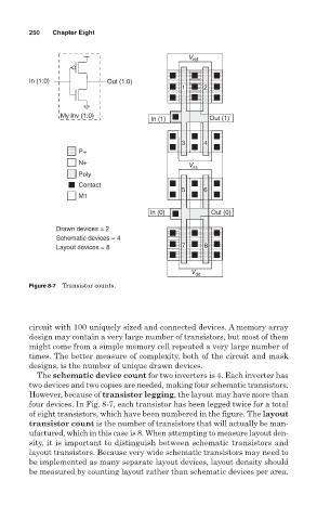
Drawn devices = 2
Schematic devices = 4
Layout devices = 8 7 8
V V V dd
Figure 8-7 Transistor counts.
circuit with 100 uniquely sized and connected devices. A memory array
design may contain a very large number of transistors, but most of them
might come from a simple memory cell repeated a very large number of
times. The better measure of complexity, both of the circuit and mask
designs, is the number of unique drawn devices.
The schematic device count for two inverters is 4. Each inverter has
two devices and two copies are needed, making four schematic transistors.
However, because of transistor legging, the layout may have more than
four devices. In Fig. 8-7, each transistor has been legged twice for a total
of eight transistors, which have been numbered in the figure. The layout
transistor count is the number of transistors that will actually be man-
ufactured, which in this case is 8. When attempting to measure layout den-
sity, it is important to distinguish between schematic transistors and
layout transistors. Because very wide schematic transistors may need to
be implemented as many separate layout devices, layout density should
be measured by counting layout rather than schematic devices per area.