
Page 281 - A Practical Guide from Design Planning to Manufacturing
P. 281
Layout 251
Layout density is often used as a measure of how successful the mask
designer has been at using the minimum area possible. However, this
metric must be very carefully applied since the best possible density may
be different for different types of circuits. Even when measured properly,
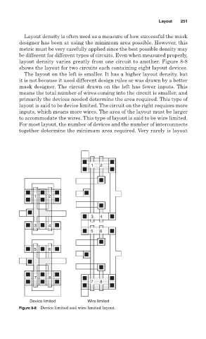
layout density varies greatly from one circuit to another. Figure 8-8
shows the layout for two circuits each containing eight layout devices.
The layout on the left is smaller. It has a higher layout density, but
it is not because it used different design rules or was drawn by a better
mask designer. The circuit drawn on the left has fewer inputs. This
means the total number of wires coming into the circuit is smaller, and
primarily the devices needed determine the area required. This type of
layout is said to be device limited. The circuit on the right requires more
inputs, which means more wires. The area of the layout must be larger
to accommodate the wires. This type of layout is said to be wire limited.
For most layout, the number of devices and the number of interconnects
together determine the minimum area required. Very rarely is layout
1 2
1 2
3 4
3 4
5 6
5 6
7 8
7 8
Device limited Wire limited
Figure 8-8 Device limited and wire limited layout.