
Page 128 - Microsensors, MEMS and Smart Devices - Gardner Varadhan and Awadelkarim
P. 128
108 STANDARD MICROELECTRONIC TECHNOLOGIES
4.6 HYBRID AND MCM TECHNOLOGIES
4.6.1 Thick Film
PCBs can also be formed on a ceramic board, and these may be referred to as
ceramic PCBs. A ceramic board, such as alumina, offers a number of advantages over
organic PCBs, because a ceramic board is much more rigid, tends to be flatter, has a
lower dielectric loss, and can withstand higher process temperatures. In addition, alumina
is a very inert material and hence is less prone to chemical attack than an organic PCB.
Ceramic PCBs can be processed in a number of different ways, such as thick-film, thin-
film, co-fired, and direct-bond copper. The most important technology is probably the thick
film. Circuit boards have been made for more than twenty years using this technology
and are usually referred to as hybrid circuits.
In thick-film technology, a number of different pastes have been developed (known as
inks), and these pastes can be screen-printed onto a ceramic base to produce interconnects,
resistors, inductors, and capacitors.
Example:
1. Artwork is generated to define the screens or stencils for the wiring layers, vias,
resistive layers, and dielectric layers.
2. Ceramic substrate is cut to size using laser drilling, and perforations that act as snapping
lines are included after the process is complete.
3. Substrate is cleaned using a sandblaster, rinsed in hot isopropyl alcohols, and heated
to 800 to 925 °C to drive off organic contaminants.
4. Each layer is then in turn screen-printed to form the multilayer structure. Each paste
is first dried at 85 to 150 °C to remove volatiles and then fired at 400 to 1000 °C.
5. The last high-temperature process performed is the resistive layer (800 to 1000 °C).
6. A low-temperature glass can be printed and fired at 425 to 525 °C to form a protective
overlayer or solder mask.
Thick-film technology has some useful advantages over other types of PCB manufacture.
The process is relatively simple - it does not require expensive vacuum equipment (like
thin-film deposition) - and hence is an inexpensive method of making circuit boards.
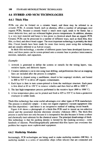
Figure 4.44 shows a photograph of a thick-film PCB used to mount an ion-selective
sensor and the associated discrete electronic circuitry (Atkinson 2001). The thick-film
process is useful here not only because it is inexpensive but also because it forms a robust
and chemically inert substrate for the chemical sensor. The principal disadvantage of thick-
film technology is that the packing density is limited by the masking accuracy - some
hundreds of microns. Photolithographically patterned thin-film layers can overcome this
problem but require more sophisticated equipment.
4.6.2 Multichip Modules
Increasingly, PCB technologies are being used to make multichip modules (MCMs). A
multichip module is a series of monolithic chips (often silicon) that are connected and