
Page 125 - Microsensors, MEMS and Smart Devices - Gardner Varadhan and Awadelkarim
P. 125
PRINTED CIRCUIT BOARD TECHNOLOGIES 105
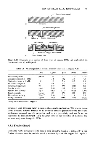
- Copper interconnect
Dielectric
-Plated through hole
(b) L —Dielectric Copper interconnect
Blind via —\ /-Buried via
Dielectric-/ Copper interconnect-
(c) Plated through hole
Figure 4.42 Schematic cross section of three types of organic PCBs: (a) single-sided; (b)
double-sided; and (c) multilayered
Table 4.8 Material properties of some common fibres used in organic PCBs
Units e-glass s-glass Quartz Aramid
Thermal expansion ppm/°C 5.0 2.8 0.54 –5.0 a
Dielectric constant at 1 MHz - 5.8 4.52 3.5 4.0
Dissipation factor at 1 MHz 10 –3 1.1 2.6 0.2 1.0
Maximum elongation % 4.8 5.5 5.0 4.5
Softening temperature °c 840 975 1420 300
Specific gravity g/cm 3 2.54 2.49 2.20 1.40
Specific heat capacity J/g.°c 0.827 0.735 0.966 1.092
Tensile strength kg/mm 350 475 200 400
Thermal conductivity W/m.°C 0.89 0.9 1.1 0.5
Young's modulus kg/mm 7400 8600 7450 13000
a
Along axis of fibre; radial is 60 ppm/°C
commonly used fibres are paper, e-glass, s-glass, quartz, and aramid. The precise choice
of the dielectric material depends on the technical demands presented by the device and
application proposed, and the properties, such as the permittivity and loss factor, are
frequently the most important. Table 4.8 gives some of the properties of the fibres that
are commonly used in organic PCBs.
4.5.2 Flexible Board
In flexible PCBs, the resin used to make a solid dielectric material is replaced by a thin
flexible dielectric material and the metal is replaced by a ductile copper foil. Again, a