
Page 123 - Microsensors, MEMS and Smart Devices - Gardner Varadhan and Awadelkarim
P. 123
MONOLITHIC MOUNTING 103
Die or chip
Al or Au wire
Die-bond material
Figure 4.38 Die- and wire-bonding technique
-TAB lead
— Chip
• Die-bond material
\
Substrate
Figure 4.39 Tape-automated bonding technique
hot thermode produces a faster throughput than wire bonding. Moreover, the reduced
inductance of a probe means that the devices can be AC-tested.
The disadvantages of TAB include the relatively high cost of the process and the need
for a large device footprint. This problem is overcome in flip-chip mounting.
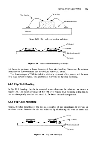
4.4.3 Flip TAB Bonding
In flip TAB bonding, the die is mounted upside down on the substrate, as shown in
Figure 4.40. The major advantage of flip TAB over regular TAB mounting is that the die
can be subsequently attached to a metal lid for better thermal management.
4.4.4 Flip-Chip Mounting
Finally, flip-chip mounting of the die has a number of key advantages. It provides an
excellent contact between the die and substrate by eliminating the wire or beam lead
Chip
Flip TAB lead
Support material
Substrate
Figure 4.40 Flip TAB technique