
Page 122 - Microsensors, MEMS and Smart Devices - Gardner Varadhan and Awadelkarim
P. 122
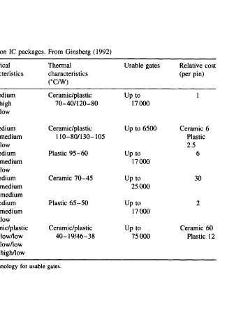
Table 4.7  Characteristics of common  IC  packages.  From  Ginsberg  (1992)
 Package  Range  of  physical  Electrical  Thermal  Usable  gates  Relative  cost
 type  dimensions  characteristics  characteristics  (per  pin)
              (°C/W)
 Through-hole  DIP  16 to  64  pins  100 mils  pin  R: medium  Ceramic/plastic  Up to  1
 pitch 0.75 to 2.3  in  body  L: high  70-40/120-80  17000
 length  0.3  to 0.7  in body  C: low
 width
 Surface  mount  SOIC  16  to  28  pins  10 mils pin  pitch  R: medium  Ceramic/plastic  Up  to 6500  Ceramic 6
 50 to 70 mils  body  length  L:  medium  110-80/130-105  Plastic
 0.3 to 0.4  in body  width  C: low               2.5
 Surface  mount OFPT  48  to  260  pins  10 mils pin  R: medium  Plastic  95-60  Up to  6
 pitch  0.65 to  1.7 in  body  L: medium  17000
 width  C: low
 Surface  mount  CLCC  28 to  84 pins 40  to  50  mils pin  R: medium  Ceramic  70-45  Up to  30
 pitch 0.45 to 0.97 in  body  L: medium  25 000
 width  C:  medium
 Surface  mount  PLCC  28 to  84 pins 50 mils pin  pitch  R: medium  Plastic  65-50  Up  to  2
 0.49  to  1.19 in  body  width  L: medium  17000
 C:  low
 Through-hole  PGA  64 to 299 pins  70 mils pin  Ceramic/plastic  Ceramic/plastic  Up to  Ceramic  60
 pitch  1.033  to  1.7 in  body  R:  low/low  40-19/46-38  75000  Plastic  12
 width  L:  low/low
 C:  high/low

 Note:  R:  Resistance,  L:  Inductance, C: Capacitance.  Assumes  1.5 urn CMOS technology  for  usable  gates.