
Page 189 - Microsensors, MEMS and Smart Devices - Gardner Varadhan and Awadelkarim
P. 189
PROCESSES USING BULK AND SURFACE MICROMACHINING 169
Si wafer
Poly,
Si wafer
(b)
Alignment PSG
window
PSG break line
PSG
Alignment 1
I window
+
p support cantilever
Si wafer
V-groove
(e)
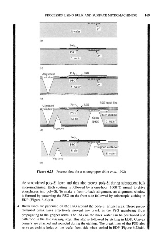
Figure 6.23 Process flow for a microgripper (Kim et al. 1992)
the sandwiched poly-Si layer and they also protect poly-Si during subsequent bulk
micromachining. Each coating is followed by a one-hour, 1000 °C anneal to drive
phosphorus into poly-Si. To make a front-to-back alignment, an alignment window
is formed by patterning the PSG on the front side followed by anisotropic etching in
EDP (Figure 6,23(c)).
4. Break lines are patterned on the PSG around the poly-Si gripper area. These prede-
termined break lines effectively prevent any crack in the PSG membrane from
propagating to the gripper arms. The PSG on the back wafer can be positioned and
patterned in the last masking step. This step is followed by etching in EDP. Convex
corners are attached and rounded during the etching. The break lines of the PSG also
serve as etching holes on the wafer front side when etched in EDP (Figure 6.23(d)).