
Page 186 - Microsensors, MEMS and Smart Devices - Gardner Varadhan and Awadelkarim
P. 186
166 SILICON MICROMACHINING: SURFACE
6.6 PROCESSES USING BOTH BULK AND SURFACE
MICROMACHINING
It is clearly possible to fabricate a variety of microsensor and MEMS devices using either
solely bulk-micromachining techniques or surface-micromachining techniques. Some of
these devices have been described here via worked examples, and a large number other
devices have been described in the literature (Gardner 1994).
However, all such devices suffer from limitations that are inherent in one or the other
of these two techniques. Taking advantages of the fabrication possibilities offered by bulk-
and surface-micromachining techniques and combining the two techniques in fabricating
MEMS devices opens up new opportunities for the fabrication of a new class of MEMS
devices that are not possible to fabricate using either of the technique alone. Several
devices have been fabricated using a combination of bulk- and surface-micromachining
processes. Two of these devices are now described in the Worked Examples 6.9 and 6.10.
15
Worked Example E6.9: Micronozzles
Objective:
Micronozzles are important in a variety of optical instruments and micromechanical
devices, for example, beam-defining elements, high-resolution ink-jet printing heads,
16
microvalves, and flow controllers . The objective in this example is to fabricate a
silicon nitride nozzle with a submicron aperture.
Process Flow:
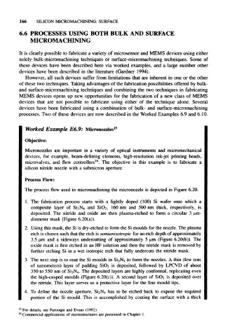
The process flow used in micromachining the micronozzle is depicted in Figure 6.20.
1. The fabrication process starts with a lightly doped (100) Si wafer onto which a
composite layer of SisN 4 and SiO 2, 160 nm and 500 nm thick, respectively, is
deposited. The nitride and oxide are then plasma-etched to form a circular 3 \im-
diameter mask (Figure 6.20(a)).
2. Using this mask, the Si is dry-etched to form the Si moulds for the nozzle. The plasma
etch is chosen such that the etch is semianisotropic for an etch depth of approximately
3.5 nm and a sideways undercutting of approximately 5 nm (Figure 6.20(b)). The
oxide mask is first etched in an HF solution and then the nitride mask is removed by
further etching Si in a wet isotropic etch that fully undercuts the nitride mask.
3. The next step is to coat the Si moulds in Si 3N 4 to form the nozzles. A thin (few tens
of nanometers) layer of padding SiO 2 is deposited, followed by LPCVD of about
350 to 550 nm of Si 3N 4. The deposited layers are highly conformal, replicating even
the high-cusped moulds (Figure 6.20(c)). A second layer of SiC»2 is deposited over
the nitride. This layer serves as a protective layer for the fine mould tips.
4. To define the nozzle aperture, Si 3N 4 has to be etched back to expose the required
portion of the Si mould. This is accomplished by coating the surface with a thick
15
For details, see Farooqui and Evans (1992).
16
Commercial applications of microstructures are presented in Chapter 1.