
Page 181 - Microsensors, MEMS and Smart Devices - Gardner Varadhan and Awadelkarim
P. 181
SURFACE MICROMACHINING USING PLASMA ETCHING 161
thermal oxide is used as an etch mask. The final rotor-stator poly-Si thickness is
2.2 urn because of the thermal oxidation used for the mask formation.
4. A second sacrificial LTO layer is grown; this provides 0.3 |im of LTO coverage on
the rotor and stator sidewalls and approximately 0.5 urn of LTO coverage on the top
surfaces. The bearing anchor is then defined and etched through the two sacrificial
oxide layers down to the electric shield below (Figure 6.14(c)).
5. A 1 urn-thick poly-Si layer is deposited, heavily doped with phosphorus, and then
patterned to form the bearing as shown in Figure 6.14(d). At this point, the completed
device is immersed in HF solution to dissolve the sacrificial LTOs and release the
rotor.
Worked Example E6.7: Gap Comb-Drive Resonant Actuator 12
Objective:
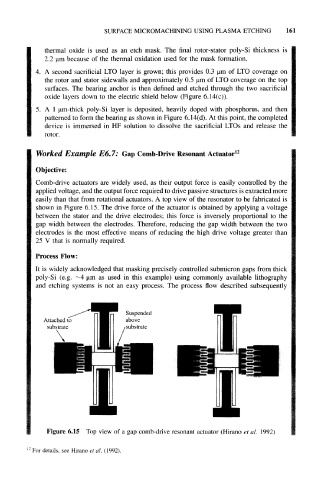
Comb-drive actuators are widely used, as their output force is easily controlled by the
applied voltage, and the output force required to drive passive structures is extracted more
easily than that from rotational actuators. A top view of the resonator to be fabricated is
shown in Figure 6.15. The drive force of the actuator is obtained by applying a voltage
between the stator and the drive electrodes; this force is inversely proportional to the
gap width between the electrodes. Therefore, reducing the gap width between the two
electrodes is the most effective means of reducing the high drive voltage greater than
25 V that is normally required.
Process Flow:
It is widely acknowledged that masking precisely controlled submicron gaps from thick
poly-Si (e.g. ~4 urn as used in this example) using commonly available lithography
and etching systems is not an easy process. The process flow described subsequently
Suspended
Attached to above
substrate substrate
Figure 6.15 Top view of a gap comb-drive resonant actuator (Hirano et al. 1992)
For details, see Hirano et al. (1992).