
Page 180 - Microsensors, MEMS and Smart Devices - Gardner Varadhan and Awadelkarim
P. 180
160 SILICON MICROMACHINING: SURFACE
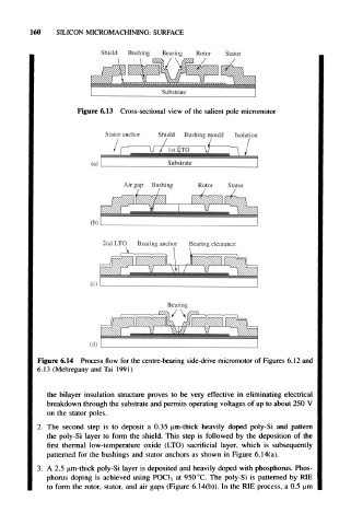
Shield Bushing Bearing Rotor Stator
Figure 6.13 Cross-sectional view of the salient pole micromotor
/,— U / / IstI TO V? / ^ / /
Stator anchor Shield Bushing mould Isolation
(a) Substrate
Air gap Bushing Rotor Stator
2nd LTO Bearing anchor Bearing clearance
Figure 6.14 Process flow for the centre-bearing side-drive micromotor of Figures 6.12 and
6.13 (Mehregany and Tai 1991)
the bilayer insulation structure proves to be very effective in eliminating electrical
breakdown through the substrate and permits operating voltages of up to about 250 V
on the stator poles.
2. The second step is to deposit a 0.35 um-thick heavily doped poly-Si and pattern
the poly-Si layer to form the shield. This step is followed by the deposition of the
first thermal low-temperature oxide (LTO) sacrificial layer, which is subsequently
patterned for the bushings and stator anchors as shown in Figure 6.14(a).
3. A 2.5 um-thick poly-Si layer is deposited and heavily doped with phosphorus. Phos-
phorus doping is achieved using POC1 3 at 950 °C. The poly-Si is patterned by RIE
to form the rotor, stator, and air gaps (Figure 6.14(b)). In the RIE process, a 0.5 (am