
Page 179 - Microsensors, MEMS and Smart Devices - Gardner Varadhan and Awadelkarim
P. 179
SURFACE MICROMACHINING USING PLASMA ETCHING 159
Centre-pin-bearing side-drive micromotor
Gap comb-drive resonant actuator
Worked Example E6.6: Centre-Pin-Bearing Side-Drive Micromotor 11
Objective:
The objective is to fabricate a centre-pin, variable-capacitance, and side-drive micro-
motor, such as the salient-pole and wobble types.
Process Flow:
The flow process in this case adds to what has already been described in the previous
Worked Examples 6.3 and 6.4. The rotor is the main component of the micromotor;
however, we also need to incorporate stator poles to form the micromotor. A variable-
capacitance side-drive micromotor clearly requires electrically conducting materials for
both the rotor and the stator. Heavy doping of the poly-Si with phosphorus to form n-type
poly-Si satisfies this requirement. In addition, the stator poles need to be electrically
isolated from the substrate, the rotor, and one another. This electrical isolation is achieved
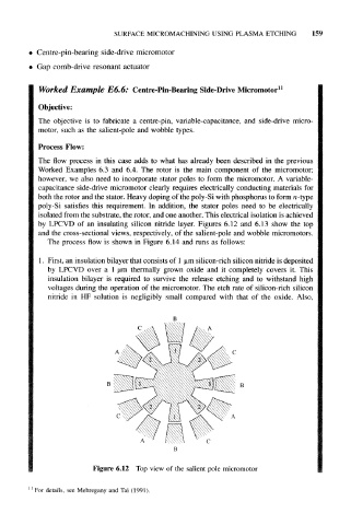
by LPCVD of an insulating silicon nitride layer. Figures 6.12 and 6.13 show the top
and the cross-sectional views, respectively, of the salient-pole and wobble micromotors.
The process flow is shown in Figure 6.14 and runs as follows:
1. First, an insulation bilayer that consists of 1 um silicon-rich silicon nitride is deposited
by LPCVD over a 1 um thermally grown oxide and it completely covers it. This
insulation bilayer is required to survive the release etching and to withstand high
voltages during the operation of the micromotor. The etch rate of silicon-rich silicon
nitride in HF solution is negligibly small compared with that of the oxide. Also,
Figure 6.12 Top view of the salient pole micromotor
" For details, see Mehregany and Tai (1991).