
Page 174 - Microsensors, MEMS and Smart Devices - Gardner Varadhan and Awadelkarim
P. 174
154 SILICON MICROMACHINING: SURFACE
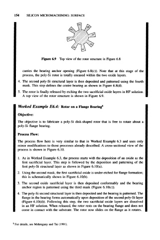
Figure 6.9 Top view of the rotor structure in Figure 6.8
carries the bearing anchor opening (Figure 6.8(c)). Note that at this stage of the
process, the poly-Si rotor is totally encased within the two oxide layers.
4. The second poly-Si structural layer is then deposited and patterned using the fourth
mask. This step defines the centre bearing as shown in Figure 6.8(d).
5. The rotor is finally released by etching the two sacrificial oxide layers in HF solution.
A top view of the rotor structure is shown in Figure 6.9.
Worked Example E6.4: Rotor on a Flange Bearing 6
Objective:
The objective is to fabricate a poly-Si disk-shaped rotor that is free to rotate about a
poly-Si flange bearing.
Process Flow:
The process flow here is very similar to that in Worked Example 6.3 and uses only
minor modifications to those processes already described. A cross-sectional view of the
process is shown in Figure 6.10.
1. As in Worked Example 6.3, the process starts with the deposition of an oxide as the
first sacrificial layer. This step is followed by the deposition and patterning of the
first poly-Si structural layer as shown in Figure 6.10(a).
2. Using the second mask, the first sacrificial oxide is under-etched for flange formation;
this is schematically shown in Figure 6.10(b).
3. The second oxide sacrificial layer is then deposited conformably and the bearing
anchor region is patterned using the third mask (Figure 6.10(c)).
4. The poly-Si second structural layer is then deposited and the bearing is patterned. The
flange in the bearing forms automatically upon deposition of the second poly-Si layer
(Figure 6.10(d)). Following this step, the two sacrificial oxide layers are dissolved
in an HF solution. When released, the rotor rests on the bearing flange and does not
come in contact with the substrate. The rotor now slides on the flange as it rotates.
6
For details, see Mehregany and Tai (1991).