
Page 173 - Microsensors, MEMS and Smart Devices - Gardner Varadhan and Awadelkarim
P. 173
SACRIFICIAL LAYER TECHNOLOGY 153
Bushing mould
Bushing Rotor
(b)
Bearing anchor
Bearing
JH Poly-Si Illllll Silicon nitride
Silicon dioxide | | (Silicon) substrate
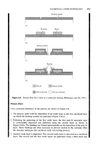
Figure 6.8 Process flow for a rotor on a centre-pin bearing (Mehregany and Tai 1991)
Process Flow:
Cross-sectional schematics of the process are shown in Figure 6.8:
1. The process starts with the deposition of an oxide layer as the first sacrificial layer
on which the bushing moulds are patterned (Figure 6.8(a)).
2. Following the patterning of the first oxide layer, the first poly-Si structural layer
is conformably deposited and patterned using the second mask as shown in
Figure 6.8(b). The bushings are formed automatically on the deposition of the poly-Si
layer. These bushings are often necessary to prevent stiction to the substrate when
the structure undergoes the sacrificial oxide wet-etching process.
3. Another oxide layer is deposited. This second oxide layer is also used as a sacrificial
layer. The second and the first oxide layers are patterned using a third mask that