
Page 188 - Microsensors, MEMS and Smart Devices - Gardner Varadhan and Awadelkarim
P. 188
168 SILICON MICROMACHINING: SURFACE
p -support cantilever
Drive arm Extension arm
Si wafer
upport cantilever
Conducting polysilicon lines
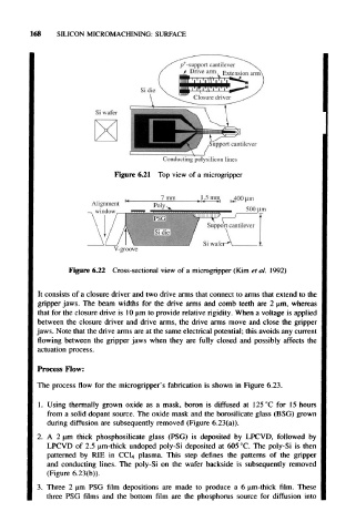
Figure 6.21 Top view of a microgripper
V-groove
Figure 6.22 Cross-sectional view of a microgripper (Kim et al. 1992)
It consists of a closure driver and two drive arms that connect to arms that extend to the
gripper jaws. The beam widths for the drive arms and comb teeth are 2 um, whereas
that for the closure drive is 10 um to provide relative rigidity. When a voltage is applied
between the closure driver and drive arms, the drive arms move and close the gripper
jaws. Note that the drive arms are at the same electrical potential; this avoids any current
flowing between the gripper jaws when they are fully closed and possibly affects the
actuation process.
Process Flow:
The process flow for the microgripper's fabrication is shown in Figure 6.23.
1. Using thermally grown oxide as a mask, boron is diffused at 125 °C for 15 hours
from a solid dopant source. The oxide mask and the borosilicate glass (BSG) grown
during diffusion are subsequently removed (Figure 6.23(a)).
2. A 2 um thick phosphosilicate glass (PSG) is deposited by LPCVD, followed by
LPCVD of 2.5 urn-thick undoped poly-Si deposited at 605 °C. The poly-Si is then
patterned by RIE in CC1 4 plasma. This step defines the patterns of the gripper
and conducting lines. The poly-Si on the wafer backside is subsequently removed
(Figure 6.23(b)).
3. Three 2 um PSG film depositions are made to produce a 6 urn-thick film. These
three PSG films and the bottom film are the phosphorus source for diffusion into