
Page 187 - Microsensors, MEMS and Smart Devices - Gardner Varadhan and Awadelkarim
P. 187
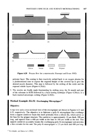
PROCESSES USING BULK  AND  SURFACE MICROMACHINING     167


                                                           v^s^^s


          (c)                              (d)


          (e)                              (f)


                         Silicon   Nitride   Oxide    Polymer

              Figure  6.20  Process flow for  a micronozzle (Farooqui and  Evans 1992)

          polymer  layer.  The  coating  is  then reactively  etched  back  in  an  oxygen  plasma  for
          a  predetermined  time  to  expose  the  required  height  of  the  covered  tip  to  give  the
          desired  nozzle  diameter.  This  step  is  followed  by  the  etching  of  the  oxide  and  the
          exposed  nitride  layers  (Figure  6.20(d)).

       5.  The  nozzles  are  finally  made  freestanding  by  etching  away  the  Si  mould  and  part
          of  the substrate  in KOH followed  by a back-sawing  technique  (Figure  6.20(e)), or a
          back-masked  anisotropic etching (Figure 6.20(f)).

       Worked  Example   E6.10:  Overhanging Microgripper 17

       Objective:
       A top view and a cross-sectional  view of the microgripper  are shown in Figures  6.21 and
       6.22,  respectively.  The  objective  is  to  fabricate  a  poly-Si  microgripper  that  overhangs
       from  a  support  cantilever beam that itself  protrudes  from  a silicon  die,  which serves  as
       the  base  for  the gripper structure.  The cantilever  is approximately  12 um thick,  500 um
       long,  and  tapered  from  a  400  um  width  at  the  base  to  100 um  width  at  the  end.  This
       support cantilever accurately locates  the overhanging poly-Si microgripper and provides
       a thin extender for the unit. The poly-Si microgripper is 2.5  um thick and 400  um long.


      For details, see  Kim et al.  (1992).