
Page 213 - Microsensors, MEMS and Smart Devices - Gardner Varadhan and Awadelkarim
P. 213
PROJECTION METHOD 193
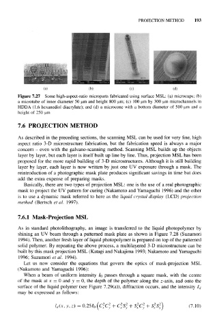
Figure 7.27 Some high-aspect-ratio microparts fabricated using surface MSL: (a) microcups; (b)
a microtube of inner diameter 50 um and height 800 um; (c) 100 um by 300 um microchannels in
HDDA (1.6 hexanediol diacrylate); and (d) a microcone with a bottom diameter of 500 um and a
height of 250 urn
7.6 PROJECTION METHOD
As described in the preceding sections, the scanning MSL can be used for very fine, high
aspect ratio 3-D microstructure fabrication, but the fabrication speed is always a major
concern - even with the galvano-scanning method. Scanning MSL builds up the objects
layer by layer, but each layer is itself built up line by line. Thus, projection MSL has been
proposed for the more rapid building of 3-D microstructures. Although it is still building
layer by layer, each layer is now written by just one UV exposure through a mask. The
reintroduction of a photographic mask plate produces significant savings in time but does
add the extra expense of preparing masks.
Basically, there are two types of projection MSL: one is the use of a real photographic
mask to project the UV pattern for curing (Nakamoto and Yamaguchi 1996) and the other
is to use a dynamic mask referred to here as the liquid crystal display (LCD) projection
method (Bertsch et al. 1997).
7.6.1 Mask-Projection MSL
As in standard photolithography, an image is transferred to the liquid photopolymer by
shining an UV beam through a patterned mask plate as shown in Figure 7.28 (Suzumori
3 994). Then, another fresh layer of liquid photopolymer is prepared on top of the patterned
solid polymer. By repeating the above process, a multilayered 3-D microstructure can be
built by this mask projection MSL (Katagi and Nakajima 1993; Nakamoto and Yamaguchi
1996; Suzumori et al. 1994).
Let us now consider the equations that govern the optics of mask-projection MSL
(Nakamoto and Yamaguchi 1996):
When a beam of uniform intensity I 0 passes through a square mask, with the centre
of the mask at x = 0 and y = 0, the depth of the polymer along the z-axis, and onto the
surface of the liquid polymer (see Figure 7.29(a)), diffraction occurs, and the intensity I d
may be expressed as follows:
2
2
2
2
2
2
2
2
l d(x, y, z) = 0.25 I 0 (C x C y+ C x S y+ S x C y + S xS y) (7.10)