
Page 216 - Microsensors, MEMS and Smart Devices - Gardner Varadhan and Awadelkarim
P. 216
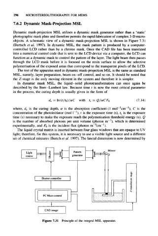
196    MICROSTEREOLITHOGRAPHY   FOR  MEMS

      7.6.2  Dynamic  Mask-Projection MSL

      Dynamic  mask-projection  MSL utilises  a  dynamic  mask  generator  rather  than  a  'static'
      photographic  mask plate and therefore  permits  the rapid fabrication  of complex  3-D  micro-
      objects.  A  schematic  view  of  a  dynamic  mask-projection  MSL  is  shown  in  Figure 7.31
      (Bertsch  et al.  1997).  In  dynamic  MSL,  the  mask  pattern  is  produced  by  a  computer-
      controlled  LCD  rather  than  by  a  chrome  mask.  Once  the  CAD  file  has  been  translated
      into a numerical control  code  that is sent  to the LCD device  via a computer,  the LCD can
      function  as a dynamic  mask  to control  the pattern of the layer. The light beam then passes
      through  the  LCD  mask  before  it  is  focused  on  the  resin  surface  to  allow  the  selective
     polymerisation  of the exposed  areas  that correspond  to the transparent pixels of the  LCD.
        The rest of the apparatus used in dynamic mask-projection MSL is the same as standard
     MSL,  namely, layer preparation,  beam on-off  control,  and so on.  It should be  noted that
     the  Z-stage  is the only  moving  element  in the  system  and therefore  it  is  simpler.
        In  dynamic  mask  MSL,  the  liquid-solid  phototransformation  can  once  again  be
     described  by  the  Beer-Lambert  law.  Because  time  t  is  now  the  most  critical  parameter
     in  the  process,  the  curing depth  is  usually  given in  the  form  of

                            =  In(t/t 0 )/aC  with  t c =                  (7.14)
                         d c                         Q/aCF 0
                                                                –1  –  1
     where,  d c  is  the  curing  depth,  a  is  the  absorption  coefficient (1 mol cm ),  C  is  the
                                       – 1
                                                                 t
     concentration of  the photoinitiator  (mol I ), t  is the exposure time (s), c  is the exposure
     time  (s) necessary  to make the exposure reach the polymerisation threshold energy (s), Q
                                                          – 3
     is  the  number of  absorbed  photons  per  unit  volume (photon m ),  which is determined
                                                       –1
                                                  –3
     experimentally,  and  F 0  is the incident flux (photon  m cm ).
        The liquid crystal  matrix is inserted  between  four glass  windows that are opaque to UV
     light; therefore,  for this  system,  it is necessary  to use a visible light source  and a  different
     set of chemical mixtures (Bertch et al.  1997). The  lateral dimension is now determined by


                     Shutter controller


                      PC Main control


                       CAD image

                      Figure  7.31  Principle of the  integral MSL apparatus