
Page 215 - Microsensors, MEMS and Smart Devices - Gardner Varadhan and Awadelkarim
P. 215
PROJECTION METHOD 195
E(x, y, z) = E 0 allows the theoretical shape of the solidified polymer after projection to
be determined.
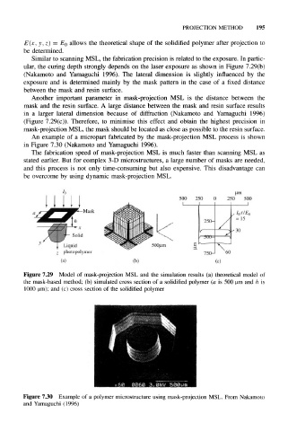
Similar to scanning MSL, the fabrication precision is related to the exposure. In partic-
ular, the curing depth strongly depends on the laser exposure as shown in Figure 7.29(b)
(Nakamoto and Yamaguchi 1996). The lateral dimension is slightly influenced by the
exposure and is determined mainly by the mask pattern in the case of a fixed distance
between the mask and resin surface.
Another important parameter in mask-projection MSL is the distance between the
mask and the resin surface. A large distance between the mask and resin surface results
in a larger lateral dimension because of diffraction (Nakamoto and Yamaguchi 1996)
(Figure 7.29(c)). Therefore, to minimise this effect and obtain the highest precision in
mask-projection MSL, the mask should be located as close as possible to the resin surface.
An example of a micropart fabricated by the mask-projection MSL process is shown
in Figure 7.30 (Nakamoto and Yamaguchi 1996).
The fabrication speed of mask-projection MSL is much faster than scanning MSL as
stated earlier. But for complex 3-D microstructures, a large number of masks are needed,
and this process is not only time-consuming but also expensive. This disadvantage can
be overcome by using dynamic mask-projection MSL.
urn
500 250 0 250 500
Mask , o' tlE
l
A
250- = 15
Y s
500-
Liquid 500um E r-»_~— \^—
photopolymer 750- 60
(a) (b)
Figure 7.29 Model of mask-projection MSL and the simulation results (a) theoretical model of
the mask-based method; (b) simulated cross section of a solidified polymer (a is 500 urn and h is
1000 urn); and (c) cross section of the solidified polymer
Figure 7.30 Example of a polymer microstructure using mask-projection MSL. From Nakamoto
and Yamaguchi (1996)