
Page 220 - Microsensors, MEMS and Smart Devices - Gardner Varadhan and Awadelkarim
P. 220
200 MICROSTEREOLITHOGRAPHY FOR MEMS
Beam
splitter
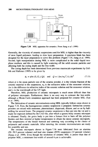
Figure 7.34 MSL apparatus for ceramics. From Jiang et al. (1999)
Generally, the viscosity of ceramic suspensions used for MSL is higher than the viscosity
of most liquid polymers, leading to slow layer preparation. A precision blade has been
designed for the layer preparation to solve this problem (Figure 7.34, Jiang et al. 1999).
Second, light transportation during MSL is more complicated in the solid-liquid two-
phase medium, and this is caused by light scattering off the solid ceramic particles and
affecting both the curing depth and the line-width.
The curing depth has been determined from previous macroscale experiments by Grif-
fith and Halloran (1995) to be given by
and Q = (7.15)
where 0 is the mean particle size of the ceramic powder, £ is the volume fraction of the
ceramic material in the suspension, HO is the refractive index of the monomer solution,
An is the difference in refractive index of the ceramic solution and the monomer solution,
and A is the wavelength of the UV light.
Therefore, MSL production of ceramic microparts is much more difficult than that
of polymer microparts. Furthermore, there is no easy way to estimate the line-width,
although a Monte-Carlo simulation approach has been proposed for ceramic MSL (Sun
etal. 1999).
The fabrication of ceramic microstructures using MSL typically follows steps shown in
Figure 7.35. First, the homogeneous ceramic suspension is prepared. Submicron ceramic
powders are mixed with monomer, photoinitiator, dispersant, diluent, and so on by ball-
milling for several hours. The prepared ceramic suspension is then put into the vat and is
ready for exposure defined by the CAD file, after which a (green) body ceramic micropart
is obtained. Finally, the green body is put into a furnace first to burn off the polymer
binders and then sintered at higher temperatures to obtain the dense ceramic microparts.
The temperatures of the binder burnout and sintering vary according to the choice of
polymeric and ceramic materials. After sintering, the ceramic microstructures are ready
for assembly and use.
The ceramic microparts shown in Figure 7.36 were fabricated from an alumina
(50-59.5 percent volume) and lead zinc titanate (PZT) suspension (33 percent volume)
(Jiang et al. 1999). Even though the resolution of ceramic MSL is poorer than that of
polymer MSL, a minimum line-width of around 6 um is achievable.