Page 105 - Modern Control Systems
P. 105

Section 2.6  Block  Diagram  Models

      Table 2.5  Continued
      Element or System                                 G(s)
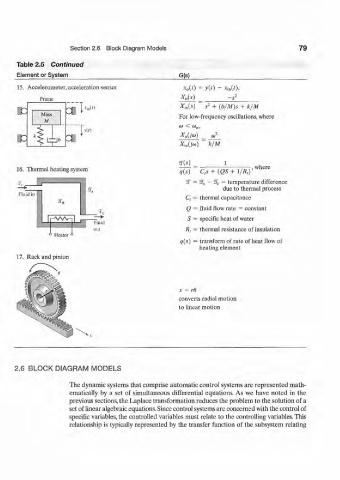
      15.  Accelerometer, acceleration sensor            *o(0  =  y{t)  -  x m{t),
             Frame                                      X 0(s)        -s*
                                                        Xin(s)  s 2  + (b/M)s  +  k/M
                                                       For low-frequency  oscillations, where
                                                        ai  <  &J„,
                                                        X 0{j(o)  or
                                                        X ia(j<o)  k/M


                                                        ^            1          ,
      16.  Thermal heating system                           —                  where
                                                        q(s)  C,s +  (QS  +  \/R,Y
                                                          2T =  %  ~  %  = temperature  difference
                                                                     due to thermal process
       Fluid ill
                                                         C, =  thermal capacitance
                                                          Q  = fluid flow rate  =  constant
                                                          S  =  specific heat  of water
                              Fluid
                              out                        R,  = thermal  resistance of insulation
                °  Heater
                                                        q(s)  = transform  of rate of heat flow of
                                                              heating element
      17.  Rack and pinion


                                                       x  =  rd
                                                       converts radial motion
                                                       to linear motion


      2.6  BLOCK DIAGRAM     MODELS

                      The dynamic systems that comprise automatic control systems are represented  math-
                      ematically  by  a set  of  simultaneous  differential  equations. As  we  have  noted  in  the
                      previous sections, the Laplace transformation reduces the problem  to the solution of a
                      set of linear algebraic equations. Since control systems are concerned  with the control of
                      specific  variables, the controlled  variables must relate to the controlling  variables. This
                      relationship  is typically represented  by  the  transfer  function  of the  subsystem  relating
   100   101   102   103   104   105   106   107   108   109   110