
Page 107 - Modern Control Systems
P. 107
Section 2.6 Block Diagram Models 81
Here the Y and R matrices are column matrices containing the I output and the J input
variables, respectively, and G is an I by J transfer function matrix. The matrix representa-
tion of the interrelationship of many variables is particularly valuable for complex multi-
variable control systems. An introduction to matrix algebra is provided on the MCS
website for those unfamiliar with matrix algebra or who would find a review helpful [21].
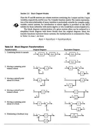
The block diagram representation of a given system often can be reduced to a
simplified block diagram with fewer blocks than the original diagram. Since the
transfer functions represent linear systems, the multiplication is commutative. Thus,
in Table 2.6, item 1, we have
X 3(s) = G 2{s)X 2{s) = G l{s)G 2{s)X x{s).
Table 2.6 Block Diagram Transformations
Transformation Original Diagram Equivalent Diagram
1. Combining blocks in cascade x. X, * l
G,(s) G 2(s) n.n~ * 3
lT[0 2
or
* i X *
G 2G l
2. Moving a summing point X, + * i
behind a block G __/^__l
x%
3. Moving a pickoff point X,
ahead of a block i " » I » G
X, I 1
««—— G +—I
4. Moving a pickoff point r~ * l X 2
behind a block x t G
I » G
X, * l 1
G
5. Moving a summing point x, + * i
ahead of a block
X-y
6. Eliminating a feedback loop x, + X-y
~\ fc G X-,
t> * l + GH
f
H <—