Page 110 - Modern Control Systems
P. 110

84              Chapter 2  Mathematical  Models of  Systems

                                                                  H 2
                                                                 [  G 4
                                  \r    —*  G x   +A       G 2            G 3  •               *• n.v)
                                    V                                                 G 4

                                                              -v  <—                        i
                                                                              •
                                                                               Hx
                                                               * 3  <—

                                                               (a)


                                                                                               »• Y(s)


                                                               (b)

                                                                   R(s)                           Y{s)
                           R > 0 - ^ G          G 2G,G 4      Y(s)              G\<h<hP*
                              -
                                           1 —  GT IGHH\ +G2G3//2      \—   GJ IG^HI^-G2GT IH2'^'G^G2G2 IG 4HT I
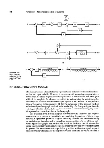
           FIGURE 2.27
           Block diagram
           reduction of the                 H,
           system of Figure
           2.26.                            (c)                                    (d)


           2.7  SIGNAL-FLOW    GRAPH   MODELS

                           Block diagrams are adequate for the representation  of the interrelationships of con-
                           trolled and input variables. However, for a system with reasonably complex interre-
                           lationships, the block  diagram reduction  procedure is cumbersome  and  often  quite
                           difficult  to  complete. An  alternative  method  for  determining  the  relationship  be-
                           tween system variables has been developed by Mason and is based on a representa-
                           tion  of the system  by line segments  [4,25]. The advantage  of the line path  method,
                           called the signal-flow graph method, is the availability  of a flow graph gain formula,
                           which provides the relation between  system variables without requiring any reduc-
                           tion procedure  or manipulation  of the flow graph.
                               The transition  from  a block  diagram  representation  to a directed  line segment
                           representation  is  easy to  accomplish  by reconsidering  the  systems  of the  previous
                           section. A  signal-flow  graph is a diagram consisting  of nodes that are connected  by
                           several  directed  branches  and  is a graphical representation  of  a  set  of linear  rela-
                           tions. Signal-flow  graphs  are  particularly  useful  for  feedback  control  systems be-
                           cause feedback theory is primarily concerned with the flow and processing of signals
                           in systems. The basic element  of a signal-flow graph is a unidirectional path segment
                           called a branch, which relates the dependency  of an input and an output variable in
   105   106   107   108   109   110   111   112   113   114   115