Page 301 - Modern Control Systems
P. 301

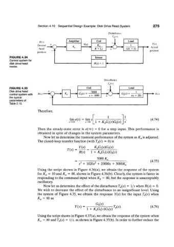
Section 4.10  Sequential Design Example: Disk  Drive Read System    275

                                                                  Disturbance
                                                                    7",,(.v)
                         /f(.v)           Amplifier        Coil              Load
                        Desired  +  "^  ,          V(s)                                     K(.v)
                        head  ^O            Ka           R +  Ls            s(Js  +  b)  - •  Actual
                       position                                                           position
       FIGURE 4.34                                        Sensor
       Control system for
       disk drive head                                   H(s) = 1
       reader.


                                                               Disturbance

       FIGURE 4.35                                   Coil                     Load
       Disk drive head                                 5000
       control system with   Ms)                G,(.v)   * +  1000       G 2 (.v) =  s(s  +  20)  • •  Yis)
       the typical
       parameters of
       Table 2.10.

                        Therefore,
                                                                 1
                                           lim e{t) =  lim s                               (4.74)
                                                          1  +   K&isMs)
                        Then  the  steady-state  error  is  e(oo)  =  0  for  a  step  input.  This  performance  is
                        obtained  in spite  of changes  in the  system parameters.
                           Now let us determine the transient performance  of the system as K a is adjusted.
                        The closed-loop transfer  function  (with T d{s)  =  0) is
                                                Y(s)        K&isMs)
                                         T(s) =
                                                R(s)   1 +  K&WGiis)
                                                           5000 K„
                                                                                          (4.75)
                                                s J  +  1020^ 2  +  20000* +  5000/C
                        Using  the  script  shown  in Figure  4.36(a), we obtain  the response  of  the  system
                        for  K a  =  10 and  K a  =  80, shown in Figure 4.36(b). Clearly, the system is faster  in
                        responding to  the command input  when K a  = 80, but the response is unacceptably
                        oscillatory.
                           Now let us determine the effect  of the disturbance T d(s)  =  1/s when R(s)  =  0.
                        We wish to  decrease  the  effect  of  the  disturbance  to  an  insignificant  level. Using
                        the  system  of  Figure  4.35, we obtain  the  response  Y(s)  for  the  input  T d(s)  when
                        K„ =  80 as
                                                          G 2(s)
                                              Y(s)  =                U')-                 (4.76)
                                                     1  +  K aG x(s)G 2(s)
                        Using the script shown in Figure 4.37(a), we obtain the response of the system when
                        K a  =  80 and T d(s)  =  1/j,  as shown in Figure 4.37(b). In order to further  reduce the
   296   297   298   299   300   301   302   303   304   305   306