
Page 275 - Modular design for machine tools
P. 275
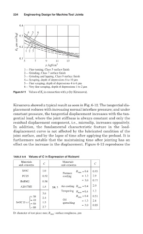
234   Engineering Design for Machine Tool Joints

                   0.4

                       4  5  6
                  K τ   mm cm 2 /kgf
                   0.3

                   0.2
                      12 3

                   0.1
                     5     7     9     11    13
                                 p, kgf/cm 2
                     1— Fine turning, Class 5 surface finish
                     2— Grinding, Class 7 surface finish
                     3— Grinding and lapping, Class 9 surface finish
                     4— Scraping, depth of depressions 8 to 10 mm
                     5— Fine scraping, depth of depressions 4 to 6 mm
                     6— Very fine scraping, depth of depressions 1 to 2 mm
               Figure 6-11 Values of K   in connection with p (by Kirsanova).


               Kirsanova showed a typical result as seen in Fig. 6-12. The tangential dis-
               placement reduces with increasing normal interface pressure; and under
               constant pressure, the tangential displacement increases with the tan-
               gential load, where the joint stiffness is always constant and only the
               residual displacement component, i.e., microslip, increases oppositely.
               In addition, the fundamental characteristic feature in the  load-
               displacement curve is not affected by the lubricated condition of the
               joint surface, and by the lapse of time after applying the preload. It is
               furthermore notable that the maintaining time after jointing has an
               effect on the increase in the displacement. Figure 6-13 reproduces the


               TABLE 6-9 Values of C in Expression of Koizumi
                     Materials              Materials
                  and concerns  C         and concerns      C
                    S45C        1.0               R   = 0.4  0.93
                                           Furnace  max
                    FC25        0.52       cooling         = 1.3  2.9
                   BsBM2        0.58                      = 3.0  0.77
                   A2017BE      1.5  SK 3  Air cooling  R max  = 0.4  2.0
                                          Tempering   = 0.4  1.2
                                3.6               R max
                           = 30                   R max  = 0.4  0.51
                                2.4
                           = 40            Oil            = 1.3  2.4
                 S45C D =       1.5        quenching
                           = 50                           = 3.0  0.85
                           = 60  2.7
               D: diameter of test piece mm; R max : surface roughness, mm