
Page 278 - Modular design for machine tools
P. 278
Engineering Design Fundamentals and Single Flat Joint Characteristics 237
Q = 400 kgf Q = 200 kgf Q = 150 kgf Q
10
P
d
1st
Equivalent solid Q = 150 kgf
8 f d
2nd loading cycle
2nd 1st loading cycle
6
3rd loading cycle
3rd 1st 4th loading cycle
P, kgf 2nd
4th Q = 200 kgf
4 3rd 1st loading cycle
4th 2nd loading cycle
4th loading cycle
Q = 400 kgf
2 Loading
1st loading cycle
4th loading cycle
Unloading
0 0.2 0.4 0.6 0.8 1.0
d, m m
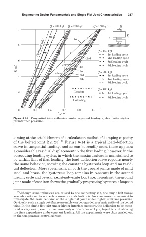
Figure 6-14 Tangential joint deflection under repeated loading cycles—with higher
preinterface pressure.
aiming at the establishment of a calculation method of damping capacity
of the bolted joint [22, 23]. 10 Figure 6-14 is a typical load-deflection
curve in tangential loading, and as can be readily seen, there appears
a considerable residual displacement in the first loading; however, in the
succeeding loading cycles, in which the maximum load is maintained to
be within that of first loading, the load-deflection curve repeats nearly
the same behavior, showing the constant hysteresis loop and no resid-
ual deflection. More specifically, in both the ground joints made of mild
steel and brass, the hysteresis loop remains in constant in the second
loading cycle and beyond, i.e., steady-state loop type. In contrast, the ground
joint made of cast iron shows the gradually progressing hysteresis loops in
10
Although some influences are caused by the connecting bolt, the single bolt-flange
assembly with uniform interface pressure distribution is, from one aspect, convenient to
investigate the basic behavior of the single flat joint under higher interface pressure.
Obviously, such a single bolt-flange assembly can be regarded as a basic entity of the bolted
joint. In the single flat joint under higher interface pressure, the deflection to be meas-
ured is very small, even in maximum only on the order of 1 m, together with showing
the time dependence under constant loading. All the experiments were thus carried out
in the temperature-controlled room.