
Page 307 - Book Hosokawa Nanoparticle Technology Handbook
P. 307
FUNDAMENTALS CH. 5 CHARACTERIZATION METHODS FOR NANOSTRUCTURE OF MATERIALS
Fz the cantilever is known. The force is defined by the
equation:
d Fz k Z (5.3.2)
The force curve provides a clue to determine the opti-
mum setpoint for getting clear image. The shape and
b a
Fz =0 z reproducibility of the force curve is used for the
f detection of unstable contact between the tip and sur-
c face, called “false engage”, which disturbs imaging.
Set point The jump-in force sometimes damages the surface of
soft sample. Measurement in vacuum and liquid
decreases jump-in force due to capillary force of
Δz water layer on the sample surface and enables imag-
e ing with small setpoint to reduce the possibility of
damage to the sample surface.
5.3.1.4 Topographic imaging 1: contact mode
Two primary modes of imaging are contact mode and
dynamic mode. In the contact mode, the tip scans while
it is in mechanical contact with the sample surface.
a b c
An electronic feedback control of the Z voltage
applied to piezoelectric scanner keeps the resulting
deflection corresponding to desired setpoint shown in
Fig. 5.3.5 by adjusting the z position of the cantilever.
The tip scans along x-axis with recording of the x
position, x and z displacement of the cantilever, z.
d e f
During scanning, the deflection of the cantilever is
constant ( z z ). The plot of x versus z shows
2
1
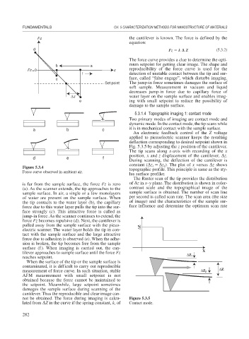
Figure 5.3.4 topographic profile. This principle is same as the sty-
Force curve observed in ambient air.
lus surface profiler.
The Ruster scan of the tip provides the distribution
is far from the sample surface, the force Fz is zero of z in x–y plane. The distribution is shown in color-
(a). As the scanner extends, the tip approaches to the contrast scale and the topographical image of the
sample surface. In air, a single or a few monolayers sample surface is obtained. The number of scan line
of water are present on the sample surface. When per second is called scan rate. The scan area (the size
the tip contacts to the water layer (b), the capillary of image) and the characteristics of the sample sur-
force due to this water layer pulls the tip into the sur- face influence and determine the optimum scan rate
face strongly (c). This attractive force is called as
jump-in force. As the scanner continues to extend, the
force Fz becomes repulsive (d). Next, the cantilever is
pulled away from the sample surface with the piezo- ΔZ
electric scanner. The water layer holds the tip in con-
tact with the sample surface and the large attractive
force due to adhesion is observed (e). When the adhe-
sion is broken, the tip becomes free from the sample
surface (f). When imaging is carried out, the can-
tilever approaches to sample surface until the force Fz ΔZ X
reaches setpoint. 1
When the surface of the tip or the sample surface is
contaminated, it is difficult to carry out reproducible
measurement of force curve. In such situation, stable ΔZ 2 ΔZ
AFM measurement with small setpoint is not
obtained because the force cannot be maintained to
the setpoint. Meanwhile, large setpoint sometimes
damages the sample surface during scanning of the
cantilever. Thus the reproducible and clear image can-
not be obtained. The force during imaging is calcu- Figure 5.3.5
lated from Z in the curve if the spring constant, k, of Contact mode.
282