
Page 310 - Book Hosokawa Nanoparticle Technology Handbook
P. 310
5.3 SURFACE STRUCTURE FUNDAMENTALS
y
z
Three dimensional
x imaging
STM tip
(a) (b)
x-y scanning Feedback
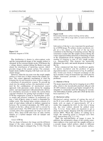
circuit Figure 5.3.10
circuit
Relationship between surface tracking and tip radius
Tunnel curvature. A tip with (a) large radius curvature and (b) small
scan direction
current radius curvature.
x control amplifier
dc bias
y control x-y-z piezo voltage
scanner
fabrication of the tip is very important for good qual-
z control ity of STM image. To achieve atomic resolution, sin-
gle or a few atoms at the end of the tip must
Figure 5.3.9 contribute to the flowing of tunneling current. The tip
Schematic diagram of STM. sometimes crashes into the sample surface during the
coarse approach before detection of tunneling current
or the optimization of the imaging parameters after
The distribution is shown in color-contrast scale starting of imaging in case of very rough sample,
and the topographical image of the sample surface is e.g., nanoparticles. This destroys the atomically
obtained. In the constant-height mode, STM keeps the sharpened tip easily and needs frequent exchange of
z voltage almost constant during the Ruster scan and the tip.
obtain the distribution of tunneling current, which Some commercial tips have insufficient quality
provides image of the sample surface. The constant- for atomic resolution and the problem of aging
height mode enables imaging with high scan rate and degradation due to contamination of tip. In addition,
clearer image. they would cost much if frequent exchange of the
However, when the tip scans over the rough sample tip is needed. Using of homemade tips fabricated by
surface or wide area, it often contacts the sample sur- simple instrument provides a solution of these
face. The coarse approach mechanism is used for problems.
bringing the tip and sample to close within a range of
z movement of piezoelectric scanner. To prevent tip (1) Materials of the tip
crash into the sample surface, this mechanism is real- The major material of the tip for imaging in air is Pt/Ir
ized by the combination of mechanical coarse alloy, which is the inoxidizable platinum alloyed with
approach with precision screw driven by stepping 10–20% iridium content to get higher strength [4–6].
motor- and microapproach with piezoelectric device. Tungsten is commonly used for imaging in vacuum.
It is absolutely necessary to isolate the system from The fabrication of nickel, gold, and cobalt tip has also
external vibrations for getting high-resolution image. been reported [7–9].
STM has suspension system or stacked plate system
as simple and effective isolation. In suspension sys- (2) Mechanical cutting
tem, a slab of heavy stone or metal is suspended by Mechanical cutting consists of cutting the end of
rubber cords. The stacked plate system consists of a the Pt–Ir wire with wire cutters. The cut should be
stack of steel plates with gel or rubbery material in made with an angle of approximately 45 at a
between. For acoustical insulation, the STM unit is stroke like snapping the wire. As the wire is being
located in the box, whose inside wall is covered by cut, the wire cutters should be pulled away
sound-proof sheet. The STM units for observation in (Fig. 5.3.11a). Some skills are required to get a
vacuum and at low temperature are large in size and sharp tip for atomic imaging with the yield ratio of
heavy. Thus, these STM units have an eddy current almost 100%. When the surface of cutting tip is
damper or a hybrid damper with air damper and rough, the tunneling point is changed each time
spring [3]. after approaching (Fig. 5.3.11b).
Thus, the reproducibility of image is poor. In
5.3.2.3 STM tip addition, the asymmetric shape of the cutting some-
The tip shape influences the image and the different times induces a tip crash onto the sample surface or
image of the same sample is sometimes obtained a pseudo image called artifact, which is different
when the tip shape is changed (Fig. 5.3.10). Thus the from real image when the rough sample surface,
285