Page 302 - Rashid, Power Electronics Handbook
P. 302

292                                                                                  S. Hui and H. Chung

                 Step 2: Soft-switching criterion is                                Lr                 L

                                          V o                                                                  RL
                                    Z                        ð15:8Þ       SW
                                     r
                                        I sðmaxÞ
                                                                     Vin                      Q     D    C        Vout
                         p 
               where Z ¼   L =C is the impedance of the resonant tank.                Cr
                            r
                      r
                               r
                 For a chosen resonant frequency f , L and C can be
                                                r
                                                   r
                                                          r
               obtained from                                                                 (a)
                                          p                         L                        D
                                  2pf ¼ 1= L C               ð15:9Þ
                                     r      r  r
                                                                                                               RL
                                                                                    Cr            Lr
               15.11.2.2 Filter Component Design
                                                                     Vin          Q                      C        Vout
               The minimum conversion ratio is
                                                                                                  SW
                                               1
                    M ðminÞ  ¼ V =V sðmaxÞ  ¼               ð15:10Þ
                             o
                                      1 ÿðF =f þ T =T Þ                                      (b)
                                                   e
                                              r
                                           sw
                                                      sw
               where T sw  ¼ 1=f sw  and t is the extended period. From Eq.           Lr               D
                                    e
               (5.10), minimum t can be estimated.
                               e
                 The turn-on period of the SW1 is                                                              RL
                                                                             SW
                                                                       Vin                           L   C        Vout
                                 T onðsw1Þ  ¼ t þ 1=f r     ð15:11Þ                            Q
                                          e
                                                                                        Cr
               Inductor value L is obtained from
                                                                                             (c)

                                     T onðsw1Þ
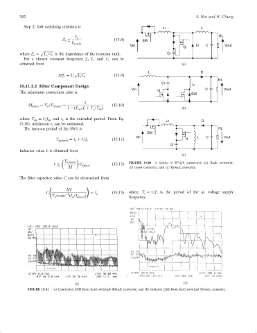
                                L           V sðmaxÞ        ð15:12Þ  FIGURE 15.40  A family of EP-QR converters: (a) Buck converter;
                                       DI                           (b) boost converter; and (c) ¯yback converter.
               The ®lter capacitor value C can be determined from
                                                !
                                      DV
                            C        ÿ1          ¼ I o      ð15:13Þ  where T ¼ 1=f is the period of the ac voltage supply
                                                                                 s
                                                                           s
                               T =p sin ðI =I sðmaxÞ Þ              frequency.
                                         o
                                s


                                          (a)                                                 (b)
                   FIGURE 15.41  (a) Conducted EMI from hard-switched ¯yback converter; and (b) radiated EMI from hard-switched ¯yback converter.
   297   298   299   300   301   302   303   304   305   306   307